Parent info
Parts you need
Affiliate links — we may earn a small commission
Try this circuit in your browser!
Run the code, press the buttons and watch what happens — before you buy any parts. No account needed.
Open in Simulator →One button. You press it. Music, voice, everything — recorded to your SD card.
Imagine this: a small matte black rectangle on your desk. You press the single button. A spinning indicator appears on the OLED. The timer starts: 00:01, 00:02, 00:03. A VU meter bar shows the audio level in real time. You speak, play a guitar, record the room. You press the button again. The file writes.
You pull out the SD card, insert it into your computer, and open REC_001.wav in your DAW. Perfect 44.1kHz, 16-bit mono audio. Professional quality. Compatible with everything.
The Teenage Engineering TP-7 field recorder costs $1,499. Yours costs $15 and teaches you exactly how WAV files work.
What you’ll need
| Part | What it does | Price |
|---|---|---|
| ESP32-S3 Dev Board | Brain. Reads audio from mic, writes to SD card simultaneously. | ~$12 |
| INMP441 MEMS microphone | I2S digital mic — captures audio as a number stream. Powered at 3.3V only. | ~$2 |
| MicroSD card module + 16GB card | Where recordings are saved. Format as FAT32 before use. | ~$3 |
| Push button | Record/stop toggle. | ~$1 |
| 0.96” OLED (SSD1306 I2C) | Shows recording status, elapsed time, VU meter, and SD free space. | ~$2 |
Total: ~$15 | Time: ~2.5 hours | Difficulty: ●●●○○
Optional but recommended: A MAX98357A I2S amp + small speaker for playback functionality (add ~$3).
How it works (60 seconds)
Think of it like a very focused data pipeline:
Microphone → [I2S protocol] → ESP32 memory buffer → [SPI protocol] → SD card
The INMP441 outputs digital audio over I2S: 44,100 samples per second, each as a 32-bit number. The ESP32 reads chunks of those numbers, converts them to 16-bit (throwing away the noisy bottom 16 bits), and writes them to a file on the SD card.
The tricky part is the WAV file format. A WAV file has a 44-byte header that describes the audio (sample rate, bit depth, channels) followed by raw audio data. You don’t know the final file size until recording ends — so you write placeholder zeros first, then seek back and fill in the correct sizes when you’re done.
That’s the whole trick. 44 bytes of metadata. Then pure audio data. That’s a WAV file.
Step 0: Prepare the SD card
Time: ~5 minutes
- Insert the microSD card into a computer
- Format as FAT32 (right-click on Windows → Format; on Mac, use Disk Utility)
- You don’t need to put any files on it — the ESP32 creates WAV files automatically
Check: Card is FAT32 formatted. Not exFAT, not NTFS, not FAT16. ESP32’s SD library requires FAT32.
Step 1: Wire it up
Time: ~20 minutes
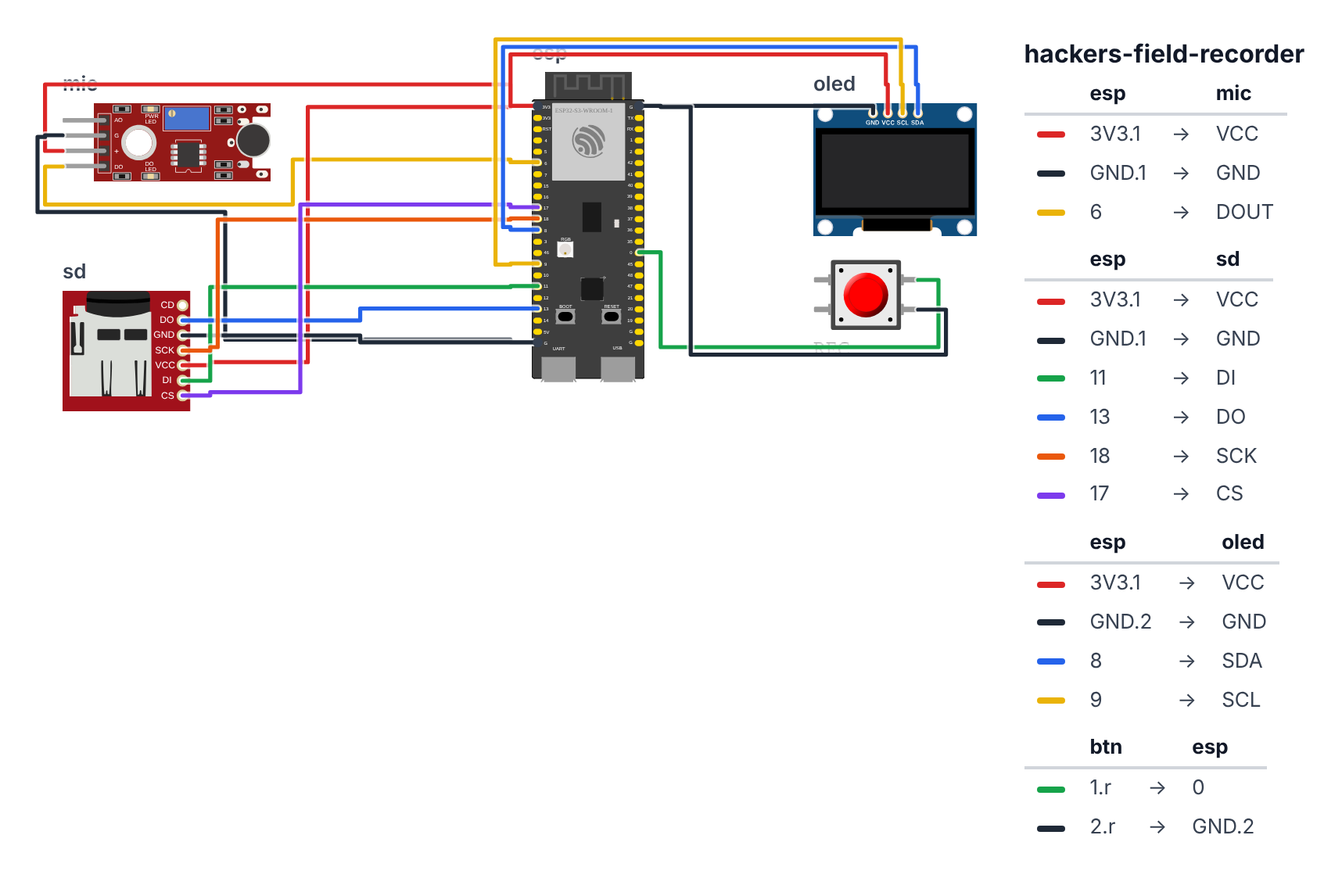
INMP441 Microphone (6 wires — 3.3V only):
- INMP441 SCK → GPIO 4 (C6: GPIO 0)
- INMP441 WS → GPIO 5 (C6: GPIO 19)
- INMP441 SD → GPIO 6 (C6: GPIO 20)
- INMP441 VDD → 3.3V — red wire, never 5V
- INMP441 GND → GND — black wire
- INMP441 L/R → GND (selects left channel)
Good to know: The wiring picture only draws the mic’s data wire (SD), because the simulator’s microphone has no SCK and WS pins. On your real board, connect all six wires listed above.
SD Card Module — SPI (5 wires): 7. SD MOSI → GPIO 11 (C6: GPIO 22) 8. SD MISO → GPIO 13 (C6: GPIO 21) 9. SD CLK → GPIO 18 (C6: GPIO 23) 10. SD CS → GPIO 17 (C6: GPIO 18) 11. SD VCC → 3.3V 12. SD GND → GND
OLED (4 wires): 13. OLED SDA → GPIO 8 (C6: GPIO 6) 14. OLED SCL → GPIO 9 (C6: GPIO 7) 15. OLED VCC → 3.3V 16. OLED GND → GND
Record Button (2 wires): 17. Button → GPIO 0 (C6: GPIO 9) | other leg → GND
Check: INMP441 on 3.3V. SD module on 3.3V (most modules have onboard regulator — check yours). GPIO 5 (C6: GPIO 19) is used for both INMP441 WS and sometimes SD CS — use GPIO 17 (C6: GPIO 18) for SD CS to avoid conflict.
Note about GPIO 0 (C6: GPIO 9): On ESP32, GPIO 0 (C6: GPIO 9) is also the boot button. Holding it during power-on enters flash mode. This is fine for normal use — just don’t hold the record button while plugging in USB.
Step 2: Upload the code
Time: ~15 minutes
Install in Arduino IDE Library Manager:
- Adafruit SSD1306 + Adafruit GFX Library — OLED display
The big picture first. The program does one job: move audio from the microphone to the SD card as fast as possible, while keeping the OLED updated and watching the button. The INMP441 microphone converts sound into a stream of numbers over a protocol called I2S — it delivers 44,100 numbers per second, each representing the air pressure at that moment. The ESP32 collects those numbers in a small bucket (the DMA buffer), then immediately writes them to the SD card. The tricky part is the WAV file. A WAV file needs a 44-byte header at the very beginning that says “this is audio at 44100 Hz, 16-bit, mono” — but you do not know the final file size until recording stops. The solution: write 44 fake zeros at the start, record everything, then at the end go back to the beginning of the file and write the real header with the correct sizes. That trick is the heart of this entire project.
// ========== CHOOSE YOUR BOARD ==========
// Uncomment the line for YOUR board:
#define BOARD_S3    // ESP32-S3-DevKitC-1
//#define BOARD_C6  // ESP32-C6-DevKitC-1
// ========================================

#ifdef BOARD_S3
  #define PIN_MIC_SCK          4
  #define PIN_MIC_WS           5
  #define PIN_MIC_SD           6
  #define PIN_SD_MOSI          11
  #define PIN_SD_MISO          13
  #define PIN_SD_CLK           18
  #define PIN_SD_CS            17
  #define PIN_BUTTON           0
  #define PIN_SDA              8
  #define PIN_SCL              9
#endif
#ifdef BOARD_C6
  #define PIN_MIC_SCK          0
  #define PIN_MIC_WS           19
  #define PIN_MIC_SD           20
  #define PIN_SD_MOSI          22
  #define PIN_SD_MISO          21
  #define PIN_SD_CLK           23
  #define PIN_SD_CS            18
  #define PIN_BUTTON           9
  #define PIN_SDA              6
  #define PIN_SCL              7
#endif

#include <Wire.h>
#include <Adafruit_SSD1306.h>
#include <SD.h>
#include <FS.h>
#include <Preferences.h>
#include <driver/i2s.h>

#define MIC_SCK    PIN_MIC_SCK
#define MIC_WS     PIN_MIC_WS
#define MIC_SD_PIN PIN_MIC_SD
#define SD_MOSI    PIN_SD_MOSI
#define SD_MISO    PIN_SD_MISO
#define SD_CLK     PIN_SD_CLK
#define SD_CS      PIN_SD_CS
#define BTN_PIN     PIN_BUTTON
#define SAMPLE_RATE 44100
#define BIT_DEPTH   16

Adafruit_SSD1306 display(128, 64, &Wire, -1);
Preferences prefs;

bool isRecording  = false;
File recFile;
int  recCounter   = 1;
unsigned long recStart = 0;

void writeWavHeader(File& f, uint32_t dataSize) {
  uint32_t totalSize  = dataSize + 36;
  uint32_t byteRate   = SAMPLE_RATE * 1 * (BIT_DEPTH / 8);
  uint16_t blockAlign = 1 * (BIT_DEPTH / 8);

  f.seek(0);
  f.write((uint8_t*)"RIFF", 4);
  f.write((uint8_t*)&totalSize,   4);
  f.write((uint8_t*)"WAVE", 4);
  f.write((uint8_t*)"fmt ", 4);
  uint32_t subchunk1 = 16;  f.write((uint8_t*)&subchunk1, 4);
  uint16_t audioFmt  = 1;   f.write((uint8_t*)&audioFmt, 2);
  uint16_t channels  = 1;   f.write((uint8_t*)&channels, 2);
  uint32_t sampleRate = SAMPLE_RATE; f.write((uint8_t*)&sampleRate, 4);
  f.write((uint8_t*)&byteRate,  4);
  f.write((uint8_t*)&blockAlign, 2);
  uint16_t bps = BIT_DEPTH; f.write((uint8_t*)&bps, 2);
  f.write((uint8_t*)"data", 4);
  f.write((uint8_t*)&dataSize,   4);
}

void setupMic() {
  i2s_config_t cfg = {
    .mode              = (i2s_mode_t)(I2S_MODE_MASTER | I2S_MODE_RX),
    .sample_rate       = SAMPLE_RATE,
    .bits_per_sample   = I2S_BITS_PER_SAMPLE_32BIT,
    .channel_format    = I2S_CHANNEL_FMT_ONLY_LEFT,
    .communication_format = I2S_COMM_FORMAT_STAND_I2S,
    .intr_alloc_flags  = ESP_INTR_FLAG_LEVEL1,
    .dma_buf_count     = 8,
    .dma_buf_len       = 512,
  };
  i2s_pin_config_t pins = {
    .bck_io_num   = MIC_SCK,
    .ws_io_num    = MIC_WS,
    .data_out_num = I2S_PIN_NO_CHANGE,
    .data_in_num  = MIC_SD_PIN
  };
  i2s_driver_install(I2S_NUM_0, &cfg, 0, NULL);
  i2s_set_pin(I2S_NUM_0, &pins);
}

void startRecording() {
  char fname[32];
  snprintf(fname, sizeof(fname), "/REC_%03d.wav", recCounter);

  recFile = SD.open(fname, FILE_WRITE);
  if (!recFile) return;

  for (int i = 0; i < 44; i++) recFile.write((uint8_t)0);

  isRecording = true;
  recStart    = millis();
}

void stopRecording() {
  isRecording = false;
  uint32_t dataSize = recFile.size() - 44;
  writeWavHeader(recFile, dataSize);
  recFile.close();

  prefs.begin("recorder", false);
  prefs.putInt("counter", ++recCounter);
  prefs.end();
}

float lastVU = 0;
void recordLoop() {
  int32_t buf[512];
  size_t bytesRead;
  i2s_read(I2S_NUM_0, buf, sizeof(buf), &bytesRead, 10);

  int samples = bytesRead / 4;
  int16_t pcm[512];
  float vuSum = 0;
  for (int i = 0; i < samples; i++) {
    pcm[i]  = (int16_t)(buf[i] >> 16);
    vuSum  += abs(pcm[i]);
  }
  recFile.write((uint8_t*)pcm, samples * 2);
  lastVU = vuSum / samples / 32768.0f;
}

int animFrame = 0;
const char* spinChars[] = {"|", "/", "-", "\\"};

void drawOLED() {
  display.clearDisplay();
  display.setTextSize(1);
  display.setCursor(0, 0);

  if (isRecording) {
    display.print("REC ");
    display.print(spinChars[animFrame % 4]);
    animFrame++;

    unsigned long elapsed = (millis() - recStart) / 1000;
    int minutes = elapsed / 60;
    int seconds = elapsed % 60;
    display.setTextSize(2);
    display.setCursor(0, 16);
    char timeStr[8];
    snprintf(timeStr, sizeof(timeStr), "%02d:%02d", minutes, seconds);
    display.print(timeStr);

    display.setTextSize(1);
    display.setCursor(0, 50);
    display.print("VU ");
    int vuBars = (int)(lastVU * 20);
    for (int i = 0; i < vuBars; i++) display.print("|");

  } else {
    display.print("READY");
    display.setTextSize(1);
    display.setCursor(0, 20);
    display.print("NEXT: REC_");
    char num[8]; snprintf(num, sizeof(num), "%03d", recCounter);
    display.print(num);
    display.print(".wav");
    display.setCursor(0, 40);

    uint64_t totalBytes = SD.totalBytes();
    uint64_t usedBytes  = SD.usedBytes();
    uint64_t freeGB     = (totalBytes - usedBytes) / (1024*1024*1024);
    display.print("FREE: ");
    display.print((int)freeGB);
    display.print("GB");
  }

  display.display();
}

void setup() {
  pinMode(BTN_PIN, INPUT_PULLUP);

  Wire.begin(PIN_SDA, PIN_SCL);
  display.begin(SSD1306_SWITCHCAPVCC, 0x3C);

  SPI.begin(SD_CLK, SD_MISO, SD_MOSI, SD_CS);
  SD.begin(SD_CS);
  setupMic();

  prefs.begin("recorder", true);
  recCounter = prefs.getInt("counter", 1);
  prefs.end();
}

void loop() {
  static bool lastBtn = HIGH;
  static unsigned long pressTime = 0;
  bool btn = digitalRead(BTN_PIN);

  if (btn == LOW && lastBtn == HIGH) pressTime = millis();
  if (btn == HIGH && lastBtn == LOW) {
    if (!isRecording) {
      startRecording();
    } else {
      stopRecording();
    }
  }
  lastBtn = btn;

  if (isRecording) {
    recordLoop();
  }

  static unsigned long lastDisplay = 0;
  if (millis() - lastDisplay > 50) {
    lastDisplay = millis();
    drawOLED();
  }
}
Line-by-line: what every line does and why
Libraries and pin defines
#include <SD.h>
#include <FS.h>
#include <Preferences.h>
#include <driver/i2s.h>
SD is the toolbox for reading and writing files on the microSD card. FS is a lower-level file system layer that SD depends on. Preferences is the toolbox for remembering things permanently — like a tiny notebook that survives power cuts. driver/i2s is the toolbox for the I2S audio protocol used by the microphone.
#define SAMPLE_RATE 44100
#define BIT_DEPTH   16
44,100 samples per second is the same rate used on CDs — it captures all frequencies the human ear can hear (up to 20,000 Hz). 16-bit depth means each sample is a number from -32768 to +32767 — 65,536 possible levels. This gives 96 dB of dynamic range (the difference between a whisper and a shout).
writeWavHeader — the 44-byte WAV recipe
void writeWavHeader(File& f, uint32_t dataSize) {
  uint32_t totalSize  = dataSize + 36;
  uint32_t byteRate   = SAMPLE_RATE * 1 * (BIT_DEPTH / 8);
  uint16_t blockAlign = 1 * (BIT_DEPTH / 8);
dataSize is the number of audio bytes recorded. totalSize is dataSize + 36 because the WAV header adds 36 bytes of overhead after the “RIFF” marker. byteRate is how many bytes per second: 44100 samples × 1 channel × 2 bytes each = 88,200 bytes/second. blockAlign is 2 — two bytes per mono 16-bit sample.
  f.seek(0);
  f.write((uint8_t*)"RIFF", 4);
  f.write((uint8_t*)&totalSize, 4);
  f.write((uint8_t*)"WAVE", 4);
  f.write((uint8_t*)"fmt ", 4);
f.seek(0) moves the write cursor back to the very beginning of the file — like rewinding a tape. Then it writes the magic words every WAV reader expects. “RIFF” tells any audio software “I’m a RIFF container file.” “WAVE” says what kind of RIFF file it is. “fmt “ (with a trailing space) starts the format description section. These are not variable — they must be exactly these bytes, exactly in this order.
  uint16_t audioFmt = 1;   f.write((uint8_t*)&audioFmt, 2);
  uint16_t channels = 1;   f.write((uint8_t*)&channels, 2);
audioFmt = 1 means PCM — uncompressed raw audio, the simplest possible format. Think of MP3 as a compressed ZIP file; PCM is the original unzipped version. channels = 1 means mono (one microphone).
setupMic — configuring the I2S microphone
.bits_per_sample = I2S_BITS_PER_SAMPLE_32BIT,The INMP441 microphone outputs 32-bit numbers even though only the top 16 bits are real audio data. The bottom 16 bits are the electronic noise floor of the chip — they just get discarded. We read 32 bits to match what the hardware sends, then throw away half of each number.
  .dma_buf_count     = 8,
  .dma_buf_len       = 512,
DMA stands for Direct Memory Access — a hardware feature that lets the microphone data flow directly into RAM without the CPU being involved every step. Think of it like a pipe from the microphone to a holding tank. dma_buf_count = 8 means there are 8 buckets in the chain. dma_buf_len = 512 means each bucket holds 512 samples. This creates a continuous, gapless pipeline — while the CPU writes one bucket to the SD card, the microphone is filling the next bucket. Without multiple buffers, you would lose audio during SD card writes.
startRecording — creating the file with placeholder zeros
for (int i = 0; i < 44; i++) recFile.write((uint8_t)0);Write 44 zero bytes as a placeholder. This reserves space at the start of the file for the WAV header that will be written later. It is like leaving a blank cover page at the front of a book before you know the title — you will come back and fill it in once you know how many pages there are.
stopRecording — finishing and fixing the header
  uint32_t dataSize = recFile.size() - 44;
  writeWavHeader(recFile, dataSize);
  recFile.close();
recFile.size() returns the total number of bytes written to the file, including the 44 placeholder bytes. Subtracting 44 gives the actual audio data size. Then writeWavHeader rewinds to byte 0 and overwrites the placeholder zeros with the correct header. recFile.close() flushes all data and closes the file safely — like clicking Save in a word processor.
  prefs.begin("recorder", false);
  prefs.putInt("counter", ++recCounter);
  prefs.end();
prefs.begin("recorder", false) opens a named key-value store in the ESP32’s protected flash memory. false means read-write mode. ++recCounter increments the counter first, then saves it. prefs.end() commits and closes. Next time the ESP32 powers on, it reads this number back in setup() so you do not overwrite previous recordings.
recordLoop — the audio pipeline in action
  int32_t buf[512];
  size_t bytesRead;
  i2s_read(I2S_NUM_0, buf, sizeof(buf), &bytesRead, 10);
i2s_read grabs a chunk of audio from the DMA buffer into buf. sizeof(buf) is 2048 bytes (512 numbers × 4 bytes each). The 10 is a timeout in milliseconds — wait up to 10ms for data.
pcm[i] = (int16_t)(buf[i] >> 16);>> 16 is a right shift — it moves all the bits 16 positions to the right, which is the same as dividing by 65,536. The INMP441 packs the real audio value into the top 16 bits of a 32-bit number. Shifting right by 16 moves those top bits down to become a normal 16-bit number. It is like reading only the first two digits of a four-digit number.
lastVU = vuSum / samples / 32768.0f;The VU meter level. vuSum is the total of all absolute sample values. Dividing by samples gives the average. Dividing by 32768 (the maximum possible 16-bit value) converts it to a 0.0–1.0 range. The OLED then draws between 0 and 20 vertical bars proportional to this level.
drawOLED — the recording status screen
    display.print(spinChars[animFrame % 4]);
    animFrame++;
spinChars is an array of four characters: |, /, -, \. animFrame % 4 cycles through 0, 1, 2, 3, 0, 1, 2, 3… forever. Each call to drawOLED shows the next character, creating a spinning animation. This lets you know recording is active even without looking at the timer.
    unsigned long elapsed = (millis() - recStart) / 1000;
    int minutes = elapsed / 60;
    int seconds = elapsed % 60;
millis() - recStart is the number of milliseconds since recording started. Dividing by 1000 gives seconds. Dividing seconds by 60 gives minutes. % 60 gives the remainder seconds (0–59). This is the standard way to convert a raw millisecond count into MM:SS format.
The whole thing in one sentence
Press once to open a WAV file on the SD card, stream 44,100 audio samples per second from the microphone into it, press again to go back and write the correct header, and the file is ready to open in any audio software in the world.
First thing to try: Upload, press the button, say your name, press again, pull the SD card, open the file in Audacity or GarageBand. Your voice should be clear and loud at the correct volume.
Check: After upload, OLED should show “READY — NEXT: REC_001.wav” and the free space on your SD card.
Step 3: Test your first recording
Time: ~3 minutes
- Press the button once — OLED shows “REC |” and the timer starts
- Speak, clap, play music near the mic — watch the VU meter respond
- Press the button again — OLED returns to “READY — NEXT: REC_002.wav”
- Remove the microSD card, insert in your computer
- Open
REC_001.wavin any audio app — standard 16-bit 44.1kHz mono WAV
Check: The file should open in Windows Media Player, QuickTime, Audacity, GarageBand, or any DAW. If it opens with silence or noise, check the INMP441 wiring and L/R pin to GND.
Step 4: Record in the field
Recording tips:
Hold the mic within 10–20cm of the sound source. The INMP441 is a directional mic — it picks up what’s in front of it well, but room reflections reduce with distance.
Watch the VU meter. If the bars never reach above 3-4 segments, the mic is too far. If they’re always at maximum and clipping, the source is too loud — move away.
Auto-naming: Files are numbered automatically: REC_001, REC_002, and the counter persists through power cycles (stored in ESP32’s flash memory via the Preferences library).
Transfer: Pull the SD card and copy files to your computer. Open in Audacity, GarageBand, Ableton, or any audio software.
What just happened (what you learned)
-
WAV file format — a RIFF container invented by Microsoft in 1991. The 44-byte header hasn’t changed since. “RIFF” + file size + “WAVE” + format parameters + “data” + data size + raw PCM bytes. Every audio player in the world reads it. You write placeholder zeros first and seek back because you don’t know the data size until recording ends.
-
PCM (Pulse-Code Modulation) — the simplest possible digital audio. A sequence of integers, each representing air pressure at that moment. The INMP441 outputs 32-bit samples; you use only the top 16 bits (right-shift by 16). The bottom 16 are noise floor. 16-bit gives 96 dB of dynamic range — covers quiet conversation to loud music.
-
SPI vs I2C vs I2S — three different serial protocols for different jobs. I2C (OLED): slow, 2 wires, for small data like display commands. SPI (SD card): fast, 4 wires, for bulk data transfer — the SD card receives 88,200 bytes per second continuously. I2S (microphone): designed specifically for audio streams, 3 wires with built-in audio timing.
-
Preferences library — persists data across reboots in ESP32’s NVS (Non-Volatile Storage), a protected area of flash memory. Without it,
recCounterresets to 1 every power cycle and you’d overwrite your recordings. With it, the ESP32 remembers how many files you’ve recorded even after the battery dies.
Level Up
Add playback. Long-press the button to play the last recording through a MAX98357A I2S amplifier and small speaker. The ESP32-audioI2S library by schreibfaul1 streams WAV files from SD to I2S. Wire a MAX98357A and speaker, add detection for long-press in the button handler.
Build the cassette tape aesthetic. The TP-7’s iconic feature is a spinning tape counter animation. Add a small OLED animation of two rotating “tape reels” — two circles with a spinning dot inside each. The dot’s speed = recording progress. Pure cosmetics, completely transforms the feel.
Add stereo recording. Add a second INMP441 with its L/R pin to 3.3V (right channel). Use I2S_CHANNEL_FMT_RIGHT_LEFT to capture both channels. Double the file size, genuine stereo — you can hear left-right placement in recordings.
★★ You completed: Field Recorder!
Troubleshooting
| Problem | Fix |
|---|---|
| OLED shows nothing after boot | Check I2C wiring: SDA→8, SCL→9 (C6: SDA→6, SCL→7). Check 3.3V power. Try I2C address 0x3D instead of 0x3C. |
| SD card not found (“READY” but SD init fails) | Check SPI wiring: MOSI→11, MISO→13, CLK→18, CS→17 (C6: MOSI→22, MISO→21, CLK→23, CS→18). Check FAT32 format (not exFAT). Check 3.3V power to SD module. |
| WAV file opens with silence | Check INMP441 wiring, especially L/R → GND. Check VDD → 3.3V (not 5V). Serial.println debug: does recordLoop() produce non-zero vuSum values? |
| Recording stops mid-way | SD card write speed issue. Try a different (faster) microSD card — Class 10 or UHS-I. |
| Timer shows wrong elapsed time | millis() is in milliseconds. Division by 1000 gives seconds. Check recStart is set to millis() at the moment recording starts. |
| Counter resets to 1 after reboot | Preferences library not saving. Check prefs.begin() / prefs.end() calls in stopRecording(). |