Parent info
Parts you need
Affiliate links — we may earn a small commission
Try this circuit in your browser!
Run the code, press the buttons and watch what happens — before you buy any parts. No account needed.
Open in Simulator →Your phone buzzes. It’s a photo of your cat doing something ridiculous.
Imagine this: you’re at school. Your phone buzzes — a Telegram notification. You open it: a photo of your cat sitting in the kitchen sink, looking deeply proud of themselves. Timestamp: 10:47am. Another buzz at 11:02: same cat, same sink, now asleep.
That’s this project. An ESP32-CAM module (it has a camera built right in) points at your pet’s favorite spot. A PIR sensor triggers a photo every time they move. The photo goes to Telegram instantly. At the end of the day: ~180 photos ready to stitch into a 7-second time-lapse of your pet’s entire day.
Build time: 2 hours. Cost: ~$19.
What you’ll need
| Part | What it does | Price |
|---|---|---|
| ESP32-CAM (AI-Thinker) | Camera + ESP32 in one module. No separate camera needed. | ~$9 |
| FTDI USB-to-Serial Programmer | Needed to upload code to the ESP32-CAM (it has no USB port). | ~$5 |
| PIR Motion Sensor HC-SR501 | Detects your pet’s body heat — triggers the photo capture. | ~$2 |
| 850nm IR LED x2 + 100Ω resistors | Infrared night vision illumination. Invisible to pets. | ~$2 |
| 2N2222 NPN Transistor + 1kΩ resistor | Switches the IR LEDs — GPIO can’t drive LEDs directly. The 1kΩ resistor goes between GPIO 12 and the transistor’s Base. | ~$0.50 |
| Light sensor module (LDR with a DO pin and a small knob) | Tells the board “dark” or “light” — auto-switches to night vision mode. A bare photoresistor won’t work here (see Step 2). | ~$1 |
You also need: a Telegram account (free), home WiFi, and the free Arduino IDE.
Total: ~$19 | Time: ~2 hours | Difficulty: ●●●○○
ESP32-CAM is different: Unlike other ESP32 boards, the ESP32-CAM has no USB port. You upload code using a separate FTDI programmer. Also, it has fewer free GPIO pins — use exactly the ones listed.
How it works (60 seconds)
Think of it like a security camera that texts you photos instead of recording to a hard drive. The PIR sensor detects motion. The ESP32-CAM captures a JPEG image in about 50ms. Then it sends that JPEG to Telegram using the same API that lets you send photos from a chat. You receive it on your phone like any other message.
Every 5 minutes it also sends a “time-lapse frame” regardless of motion — so you get a complete record of the day. Collect 180 of those photos and one ffmpeg command turns them into a video.
Night vision works automatically: a light sensor module (a photoresistor with its own little “dark or light?” chip) checks the room brightness. When it goes dark, the ESP32 switches the camera to grayscale mode and turns on two 850nm infrared LEDs (invisible to your pet, visible to the camera sensor).
Step 0: Create your Telegram bot
Time: ~5 minutes
You need a Telegram bot before anything else:
- Open Telegram on your phone. Search for @BotFather.
- Type
/newbot. Give it a name: “PetCamBot” (or anything you like). - BotFather gives you a bot token — a long string like
7234567890:AAFxxx.... Copy it exactly. - Start a chat with your new bot (search for its name in Telegram). Send it “Hello.”
- Search for @userinfobot in Telegram. Start a chat with it. It replies with your Chat ID — a number like
123456789. Copy it.
Keep both values — you’ll paste them into the code.
Step 1: Wire the FTDI programmer for uploading
Time: ~10 minutes
The ESP32-CAM needs this wiring to receive code uploads:
| FTDI | ESP32-CAM |
|---|---|
| TX | GPIO 3 (RX) |
| RX | GPIO 1 (TX) |
| GND | GND |
| 5V | 5V |
| — | IO0 → GND (during upload only — a jumper wire) |
Critical: Connect IO0 to GND only during upload. This puts the ESP32-CAM into bootloader mode. After uploading, disconnect the IO0-to-GND jumper and press the reset button on the board.
In Arduino IDE, select board: “AI Thinker ESP32-CAM” — not a regular ESP32 board.
Step 2: Wire the sensors
Time: ~15 minutes
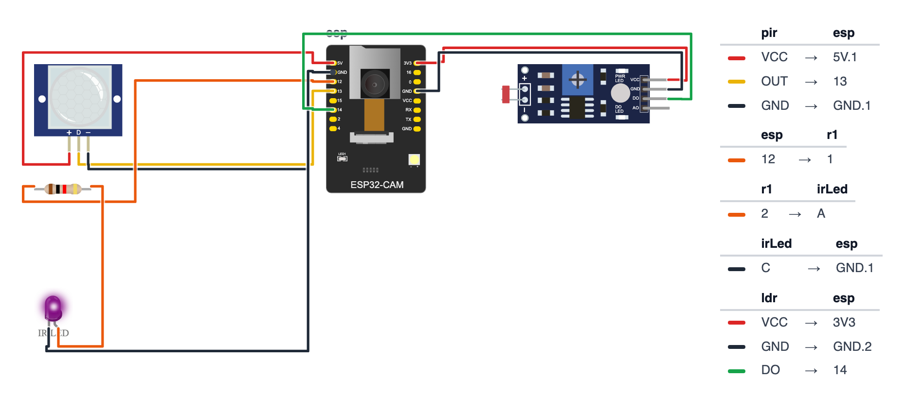
After uploading (remove the IO0 jumper), wire the sensors. These pins are for the AI-Thinker ESP32-CAM — the camera already uses almost every other pin, so use exactly these: GPIO 13 (PIR), GPIO 12 (IR LEDs), GPIO 14 (light module).
PIR Sensor HC-SR501:
- PIR VCC → board 5V — red wire
- PIR OUT → board GPIO 13 — yellow wire
- PIR GND → board GND — black wire
IR LED Night Vision circuit (via transistor — required): 4. 1kΩ resistor from GPIO 12 → 2N2222 Base 5. For each IR LED: board 5V → 100Ω resistor → IR LED (+, long leg); IR LED (−, short leg) → 2N2222 Collector 6. 2N2222 Emitter → GND
Good to know: the wiring picture leaves out the transistor (the drawing tool has no transistor part), so there the 1kΩ resistor seems to go from GPIO 12 straight to one IR LED. Build the real circuit exactly as in steps 4–6: 1kΩ to the Base, each IR LED with its own 100Ω resistor from 5V to the Collector, Emitter to GND.
Light sensor module (LDR module with a DO pin): 7. Module VCC → board 3.3V (not 5V — then the DO pin sends safe 3.3 V signals) 8. Module GND → board GND 9. Module DO → board GPIO 14 — leave the module’s AO pin empty
Why the transistor? GPIO pins can only output ~12mA. IR LEDs need more. The 2N2222 transistor acts like a switch: a small GPIO signal controls a larger current path. GPIO 12 → 1kΩ → Base (only about 2.6mA from the pin — enough to switch the transistor fully on for both IR LEDs). IR LEDs → Collector-to-Emitter. This is a fundamental electronics pattern.
Why GPIO 12 for the IR LEDs? GPIO 12 must be LOW when the ESP32-CAM starts, or it won’t boot. The transistor circuit doesn’t pull it HIGH, so an output is fine there — but never a sensor that might send HIGH. That’s why the light module goes on GPIO 14.
Why a module with a DO pin and not a bare photoresistor? On the ESP32-CAM, every free pin belongs to the chip’s second analog converter (ADC2) — and ADC2 can’t do
analogReadwhile Wi-Fi is on. The light module solves this: its own little comparator chip compares the light with the level you set on its knob and sends a simple HIGH (darker than your setting) or LOW (brighter) on DO. The board reads it withdigitalRead— no analog needed.
Set the darkness level with the module’s knob: power the board, make the room as dark as it is when you want night vision to start (close the curtains, switch off the lights), then turn the small knob (potentiometer) on the module slowly with a screwdriver until its DO LED just switches. Now anything darker than that counts as night. Turn it the other way if night mode comes on too early.
Step 3: Upload the code
Time: ~15 minutes
No additional libraries needed — esp_camera.h and WiFiClientSecure are both built into the ESP32 Arduino core.
Re-connect IO0 to GND for uploading, then disconnect afterward.
The big picture first. This program does three things at once.
- Motion detection: the PIR sensor detects your pet’s body heat. The moment they move across its view, the ESP32 captures a photo.
- Photo sending: the photo is sent to a Telegram bot — the same service you use for messaging — so it arrives on your phone like a chat message.
- Time-lapse: every 5 minutes, a photo is sent regardless of motion. Collect these all day and you have a complete diary of what your pet did while you were at school.
Night vision works automatically: a light sensor (LDR) measures room brightness every 5 minutes. When it gets dark, the code switches the camera to grayscale and turns on two infrared LEDs that humans cannot see but the camera can.
// Note: This project requires ESP32-S3 or ESP32-CAM (camera)

#include "esp_camera.h"
#include <WiFi.h>
#include <WiFiClientSecure.h>

#define PWDN_GPIO_NUM  32
#define RESET_GPIO_NUM -1
#define XCLK_GPIO_NUM   0
#define SIOD_GPIO_NUM  26
#define SIOC_GPIO_NUM  27
#define Y9_GPIO_NUM    35
#define Y8_GPIO_NUM    34
#define Y7_GPIO_NUM    39
#define Y6_GPIO_NUM    36
#define Y5_GPIO_NUM    21
#define Y4_GPIO_NUM    19
#define Y3_GPIO_NUM    18
#define Y2_GPIO_NUM     5
#define VSYNC_GPIO_NUM 25
#define HREF_GPIO_NUM  23
#define PCLK_GPIO_NUM  22

const char* ssid     = "YourWiFiName";
const char* password = "YourWiFiPassword";
const char* botToken = "YOUR_BOT_TOKEN_HERE";
const char* chatId   = "YOUR_CHAT_ID_HERE";

const int PIN_PIR    = 13;
const int PIN_IR_LED = 12;
const int PIN_LDR    = 14;

bool nightMode = false;

unsigned long lastTimelapse = 0;
const unsigned long TIMELAPSE_INTERVAL = 300000;

void sendPhotoToTelegram(camera_fb_t* fb, String caption) {
  WiFiClientSecure client;
  client.setInsecure();

  String url      = "/bot" + String(botToken) + "/sendPhoto";
  String boundary = "----ESP32CamBoundary";

  String head = "--" + boundary + "\r\nContent-Disposition: form-data; "
    "name=\"chat_id\"\r\n\r\n" + String(chatId) + "\r\n" +
    "--" + boundary + "\r\nContent-Disposition: form-data; "
    "name=\"caption\"\r\n\r\n" + caption + "\r\n" +
    "--" + boundary + "\r\nContent-Disposition: form-data; "
    "name=\"photo\"; filename=\"photo.jpg\"\r\nContent-Type: image/jpeg\r\n\r\n";
  String tail = "\r\n--" + boundary + "--\r\n";

  if (!client.connect("api.telegram.org", 443)) {
    Serial.println("Telegram connection failed");
    return;
  }

  int totalLen = head.length() + fb->len + tail.length();

  client.println("POST " + url + " HTTP/1.1");
  client.println("Host: api.telegram.org");
  client.println("Content-Type: multipart/form-data; boundary=" + boundary);
  client.println("Content-Length: " + String(totalLen));
  client.println("Connection: close");
  client.println();

  client.print(head);
  client.write(fb->buf, fb->len);
  client.print(tail);

  delay(1000);
  Serial.println("Photo sent!");
}

void captureAndSend(String reason) {
  sensor_t *s = esp_camera_sensor_get();

  if (nightMode) {
    s->set_special_effect(s, 2);
    digitalWrite(PIN_IR_LED, HIGH);
  } else {
    s->set_special_effect(s, 0);
    digitalWrite(PIN_IR_LED, LOW);
  }

  camera_fb_t *fb = esp_camera_fb_get();
  if (!fb) { Serial.println("Camera capture failed"); return; }

  String caption = reason + (nightMode ? " [Night Vision]" : "");
  sendPhotoToTelegram(fb, caption);
  esp_camera_fb_return(fb);
}

void setup() {
  Serial.begin(115200);
  pinMode(PIN_PIR,    INPUT);
  pinMode(PIN_LDR,    INPUT);
  pinMode(PIN_IR_LED, OUTPUT);
  digitalWrite(PIN_IR_LED, LOW);

  camera_config_t config;
  config.ledc_channel = LEDC_CHANNEL_0;
  config.ledc_timer   = LEDC_TIMER_0;
  config.pin_d0 = Y2_GPIO_NUM; config.pin_d1 = Y3_GPIO_NUM;
  config.pin_d2 = Y4_GPIO_NUM; config.pin_d3 = Y5_GPIO_NUM;
  config.pin_d4 = Y6_GPIO_NUM; config.pin_d5 = Y7_GPIO_NUM;
  config.pin_d6 = Y8_GPIO_NUM; config.pin_d7 = Y9_GPIO_NUM;
  config.pin_xclk     = XCLK_GPIO_NUM;
  config.pin_pclk     = PCLK_GPIO_NUM;
  config.pin_vsync    = VSYNC_GPIO_NUM;
  config.pin_href     = HREF_GPIO_NUM;
  config.pin_sscb_sda = SIOD_GPIO_NUM;
  config.pin_sscb_scl = SIOC_GPIO_NUM;
  config.pin_pwdn     = PWDN_GPIO_NUM;
  config.pin_reset    = RESET_GPIO_NUM;
  config.xclk_freq_hz = 20000000;
  config.pixel_format = PIXFORMAT_JPEG;
  config.frame_size   = FRAMESIZE_VGA;
  config.jpeg_quality = 12;
  config.fb_count     = 1;

  esp_err_t err = esp_camera_init(&config);
  if (err != ESP_OK) {
    Serial.printf("Camera init failed: 0x%x\n", err);
    return;
  }

  WiFi.begin(ssid, password);
  while (WiFi.status() != WL_CONNECTED) delay(500);
  Serial.println("Connected! Pet cam is live.");

  camera_fb_t *fb = esp_camera_fb_get();
  if (fb) { sendPhotoToTelegram(fb, "Pet cam online!"); esp_camera_fb_return(fb); }
}

void loop() {
  unsigned long now = millis();

  static unsigned long lastLightCheck = 0;
  if (now - lastLightCheck > 300000) {
    lastLightCheck = now;
    int ldr = digitalRead(PIN_LDR);
    nightMode = (ldr == HIGH);
    Serial.println("Light: " + String(ldr) + (nightMode ? " (Night)" : " (Day)"));
  }

  static bool pirWas = false;
  bool pirNow = digitalRead(PIN_PIR) == HIGH;
  if (pirNow && !pirWas) {
    Serial.println("Motion! Capturing...");
    captureAndSend("Motion detected");
    delay(10000);
  }
  pirWas = pirNow;

  if (now - lastTimelapse > TIMELAPSE_INTERVAL) {
    lastTimelapse = now;
    captureAndSend("Time-lapse");
  }
}
Line-by-line: what every line does and why
Lines 1–3: Borrowing the camera and network tools
#include "esp_camera.h"
#include <WiFi.h>
#include <WiFiClientSecure.h>
esp_camera.h is the instruction book for the camera hardware built into the ESP32-CAM board. WiFiClientSecure adds HTTPS support — Telegram’s servers only accept encrypted connections, so a plain WiFi connection won’t work.
Lines 5–22: The camera’s secret pin map
#define PWDN_GPIO_NUM  32
#define RESET_GPIO_NUM -1
...
#define PCLK_GPIO_NUM  22
The ESP32-CAM board has a camera chip (OV2640) soldered to specific pins on the PCB — you can’t change these. #define gives each pin number a readable name. RESET_GPIO_NUM = -1 means “there is no reset pin.” You copy this block exactly — never change these numbers.
Lines 24–30: Your Telegram credentials
const char* botToken = "YOUR_BOT_TOKEN_HERE";
const char* chatId   = "YOUR_CHAT_ID_HERE";
Your bot token is like a username + password for your bot — it comes from @BotFather in Telegram. Your chat ID is your personal Telegram account number — it comes from @userinfobot. Together they tell the code “send the photo to this person’s Telegram.”
The pins and the night vision flag
const int PIN_PIR    = 13;
const int PIN_IR_LED = 12;
const int PIN_LDR    = 14;

bool nightMode = false;
The ESP32-CAM’s camera uses almost all of the chip’s pins, so these three come from the few free ones on its header. There is no darkness number in the code: the light module’s knob is the threshold. Its DO pin is HIGH when the room is darker than your knob setting and LOW when it’s brighter. nightMode is the flag that switches between color camera and grayscale + IR LEDs.
sendPhotoToTelegram(): how a photo becomes a Telegram message
WiFiClientSecure client;
client.setInsecure();
WiFiClientSecure is like an encrypted phone line. setInsecure() skips verifying the server’s identity certificate — for a personal pet cam this is fine. Think of it like calling someone without checking their caller ID.
String boundary = "----ESP32CamBoundary";When you send a file over the web, you need a “separator” string to show where one piece of data ends and the next begins. This boundary string acts like a divider wall — it appears between the chat ID, the caption text, and the actual photo bytes.
client.println("POST " + url + " HTTP/1.1");
client.println("Host: api.telegram.org");
client.println("Content-Type: multipart/form-data; boundary=" + boundary);
This is raw HTTP — the same format a browser uses when you upload a photo to a website. POST means “I’m sending data TO the server.” The lines up to the blank println() are the headers (envelope information). After the blank line comes the actual data (the photo).
client.write(fb->buf, fb->len);fb->buf is a pointer to where the JPEG photo bytes are stored in memory. fb->len is how many bytes it is. write sends all those raw bytes down the connection to Telegram’s server.
esp_camera_fb_return(fb);This is the most important cleanup line. The camera stores photos in a reserved memory region called a “frame buffer.” fb_get() locks that region and gives you access. fb_return() unlocks it so the next photo can be captured. If you forget this, the second call to esp_camera_fb_get() returns nothing and the camera stops working.
captureAndSend(): prepare and fire
sensor_t *s = esp_camera_sensor_get();
if (nightMode) {
  s->set_special_effect(s, 2);
  digitalWrite(PIN_IR_LED, HIGH);
}
esp_camera_sensor_get() returns a pointer to the camera sensor settings. set_special_effect(s, 2) switches to grayscale mode — which works much better with infrared light than color mode does. HIGH on the IR LED pin turns on the infrared lights — invisible to your pet, visible to the camera.
setup(): preparing the camera configuration
camera_config_t config;
config.pin_d0 = Y2_GPIO_NUM; ...
config.pixel_format = PIXFORMAT_JPEG;
config.frame_size   = FRAMESIZE_VGA;
config.jpeg_quality = 12;
camera_config_t is a container that holds all the camera settings. You fill in every field, then pass it to esp_camera_init(&config) which starts the camera hardware. PIXFORMAT_JPEG means the camera chip compresses photos to JPEG in hardware — much faster than doing it in software. jpeg_quality = 12 means good quality (lower numbers = better quality on this scale).
loop(): three tasks running in turns
int ldr = digitalRead(PIN_LDR);
nightMode = (ldr == HIGH);
Every 5 minutes the code reads the light module’s DO pin. HIGH means “darker than the knob setting”, so night mode switches on. Serial Monitor shows Light: 1 (Night) or Light: 0 (Day).
static bool pirWas = false;
bool pirNow = digitalRead(PIN_PIR) == HIGH;
if (pirNow && !pirWas) {
  captureAndSend("Motion detected");
  delay(10000);
}
pirWas = pirNow;
static means pirWas remembers its value between loop calls — like a sticky note that doesn’t get erased. The condition pirNow && !pirWas detects the exact moment the PIR switches from no-motion to motion — the rising edge. Without this pattern, the code would send a new photo every millisecond while motion is happening. The 10-second delay prevents flooding your phone with identical photos.
if (now - lastTimelapse > TIMELAPSE_INTERVAL) {
  lastTimelapse = now;
  captureAndSend("Time-lapse");
}
Every 5 minutes (300,000 milliseconds), send a time-lapse frame regardless of motion. Collect all the time-lapse photos and one ffmpeg command turns them into a video of your pet’s day.
The whole thing in one sentence
When powered on, the camera connects to WiFi, sends a startup photo to Telegram, then watches for motion and sends a photo every time your pet moves — plus one every 5 minutes no matter what, and switches to night vision automatically when the room gets dark.
First thing to try: after uploading, open Telegram. You should receive “Pet cam online!” with a photo within 30 seconds. Walk in front of the PIR sensor — your phone should buzz within 2 seconds.
Check: After uploading, disconnect IO0 from GND and press the reset button. Open Serial Monitor — you should see “Connected! Pet cam is live.” Then your Telegram should receive “Pet cam online!” with a test photo.
Step 4: Mount the camera and aim it
Time: ~10 minutes
A small goose-neck phone holder works perfectly. Position the camera pointing at your pet’s favorite spot — their usual sleeping place, food bowl area, or the couch they’re not supposed to be on.
For the IR LEDs: Position them to illuminate the camera’s field of view. They should flank the camera lens so the light covers the same area the camera sees.
Make sure the camera is stable — motion blur from a wobbly mount is the most common photo quality problem.
Check: Walk past the camera. Within 1–2 seconds, check your Telegram — you should receive a “Motion detected” photo. Leave it for 5 minutes and confirm a “Time-lapse” photo arrives.
What just happened (what you learned)
- Multipart HTTP POST — when you upload a photo to a website, your browser sends a multipart POST: the file is broken into named “parts” separated by a boundary string. The Telegram API expects this exact format. The code builds the boundary, headers, and body manually — this is raw HTTP, no library needed.
- Frame buffers and
esp_camera_fb_return()— the camera stores frames in a reserved RAM region.esp_camera_fb_get()locks that region and gives you a pointer to the JPEG data. If you never callfb_return(fb), the buffer stays locked and the next capture fails with “Camera capture failed.” Always return the buffer immediately after use. WiFiClientSecurewithsetInsecure()— HTTPS checks the server’s SSL certificate to prevent fake servers.setInsecure()skips that check. For a personal pet cam, this is fine — you’re not sending passwords. For anything handling sensitive data, use proper certificate verification.- 850nm IR LEDs and the camera — 850nm is outside the range human eyes can detect (humans see up to ~700nm). But the OV2640 camera sensor detects up to 1000nm. So the IR LEDs illuminate the scene invisibly to your pet, but the camera sees it clearly in grayscale mode.
Level Up
Make the time-lapse: At the end of each day, save all the time-lapse photos from Telegram to a folder on your computer. Then run:
ffmpeg -r 24 -pattern_type glob -i "*.jpg" timelapse.mp4288 photos at 24fps = 12 seconds of your pet’s entire day. Free on any OS — ffmpeg.org.
Save to SD card: The ESP32-CAM has a built-in SD card slot. Start it in 1-bit mode with SD_MMC.begin("/sdcard", true) — it then uses GPIO 2, 14 and 15. GPIO 14 is the light module’s pin, so for this upgrade unplug the light module and leave nightMode off (the PIR on 13 and the IR LEDs on 12 can stay). After esp_camera_fb_get(), open a file: SD_MMC.open("/photo_" + String(millis()) + ".jpg", FILE_WRITE) and write fb->buf. Archive mode: every motion event saved locally forever.
Better photo quality: Change FRAMESIZE_VGA to FRAMESIZE_SVGA (800×600) for sharper photos, or FRAMESIZE_QVGA (320×240) if photos take too long to send. Change jpeg_quality from 12 to 6 for higher quality (larger files).
★★ You completed: Pet Cam with Motion Alerts!
Troubleshooting
| Problem | Fix |
|---|---|
| Camera init failed | IO0 still connected to GND. Disconnect it and reset. Check FTDI wiring. |
| “Pet cam online!” message never arrives | WiFi credentials wrong. Bot token or Chat ID wrong — copy them exactly from Telegram. |
| Camera capture fails | esp_camera_fb_return(fb) missing — the buffer is stuck. Check it’s in captureAndSend. Power issue — ESP32-CAM needs a stable 5V, not 3.3V. |
| Photos are blurry | Camera moving during capture. Secure the mount. Increase jpeg_quality from 12 to 8 (lower number = better). |
| No motion alerts but time-lapse works | PIR sensor not triggering. Check PIR VCC on 5V (not 3.3V). Walk past the sensor and check Serial Monitor for “Motion!” output. |
| Night vision doesn’t turn on | Turn the light module’s knob (see Step 2) until its DO LED switches when the room is dark. Check module DO → GPIO 14, VCC → 3.3V, GND → GND. The code checks the light only every 5 minutes — watch Serial Monitor for Light: 1 (Night). |
| Board won’t start after wiring | Something is pulling GPIO 12 HIGH at power-on. Only the IR LED transistor circuit may be on GPIO 12 — never a sensor. |
| Bot doesn’t receive photos | Make sure you started a conversation with your bot (send it “Hi”) — bots can’t initiate conversations. Verify chat ID is yours, not the bot’s ID. |