Parent info
Parts you need
Affiliate links — we may earn a small commission
Try this circuit in your browser!
Run the code, press the buttons and watch what happens — before you buy any parts. No account needed.
Open in Simulator →Your classmates made sculptures that sit still. Yours moves.
Art class project: create a sculpture that expresses a concept — motion, time, energy, nature. Everyone else builds something with clay, wire, or paper that sits on a pedestal and looks interesting. Perfectly fine. Very art-school.
Yours has two servo motors that continuously move different elements in rhythmic patterns, with 16 LEDs that shift colors in sync with the movement. It doesn’t just represent motion — it IS motion. And the best part: you programmed the movement. Every rotation speed, every color, every timing relationship. The art is yours in a way no other project in class can claim.
What you’ll need
| Part | What it does | Price |
|---|---|---|
| ESP32-S3-DevKitC-1 | The brain — coordinates all motion and light | ~$12 |
| SG90 servo motors (2) | Two independent moving elements | ~$6 |
| WS2812 LED ring (16 LEDs) | Synchronized color effects | ~$5 |
| Breadboard + jumper wires | Connects everything | ~$5 |
| USB-C data cable | Programming connection | ~$5 |
Total: ~$33 | Time: ~2 hours | Difficulty: ●●●○○
What is kinetic art? Kinetic art is a style where the artwork moves as part of its expression. Famous kinetic artists include Alexander Calder (mobiles), Jean Tinguely (mechanical sculptures), and Theo Jansen (wind-powered walking machines). Your project places you in that tradition — but with programmable electronics instead of mechanical wind.
How it works (60 seconds)
Both servos move in smooth programmatic patterns — not jerky back-and-forth, but smooth sine-wave motion that looks natural and organic. The LED ring displays colors that shift based on the servo positions, so light and movement are linked. You define the pattern: pendulum swing, circular orbit, breathing pulse, or your own mathematical motion function. This is called generative art — art created by algorithms you wrote.
Step 0: Design your sculpture concept
Time: ~30 minutes
What concept does your sculpture express? Choose one and build around it.
Option A — “Celestial” (planets orbiting):
- Two arms extending from a central point
- Servo 1 moves a large ring (the “planet”) in slow circles
- Servo 2 moves a small ball (the “moon”) faster
- LED ring pulses blue/purple like space
Option B — “Heartbeat” (biological rhythm):
- One element expands and contracts like breathing
- Another pulses like a heartbeat — different rhythm
- LED ring pulses red, synced to the “heart” servo
- Frame made of curved wire or bent cardboard to suggest ribcage
Option C — “Elements” (abstracted nature):
- One servo drives a “branch” with paper leaves that sway in the “wind”
- Other servo drives water-like oscillating strips of iridescent cellophane
- LED ring shifts from blue to green to represent sky-to-earth
Build the physical structure before adding electronics. Whatever your concept, the moving parts should attach to servo arms via thin wire, popsicle sticks, or lightweight cardboard.
Weight warning: SG90 servos are small. Don’t attach anything heavier than a large paperclip to the servo arm. Keep moving parts very lightweight.
Step 1: Wire it up
Time: ~10 minutes
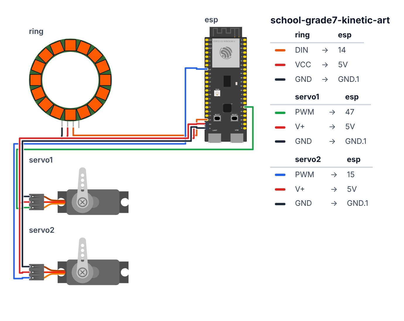
WS2812 LED Ring (3 wires):
- Ring DIN → board GPIO 14 (C6: GPIO 8) — orange wire
- Ring 5V → board 5V — red wire
- Ring GND → board GND — black wire
Servo 1 — Primary motion (3 wires): 4. Servo1 signal (orange) → board GPIO 47 (C6: GPIO 7) — green wire 5. Servo1 VCC (red) → board 5V — red wire 6. Servo1 GND (brown) → board GND — black wire
Servo 2 — Secondary motion (3 wires): 7. Servo2 signal (orange) → board GPIO 15 (C6: GPIO 19) — blue wire 8. Servo2 VCC (red) → board 5V — red wire 9. Servo2 GND (brown) → board GND — black wire
Check: Total 9 wire connections. GPIO 47 (C6: GPIO 7) = Servo1, GPIO 15 (C6: GPIO 19) = Servo2, GPIO 14 (C6: GPIO 8) = LEDs.
Step 2: Flash the code
Time: ~20 minutes
Install Adafruit NeoPixel and ESP32Servo libraries.
Here is the big picture. This program creates mathematical motion — art driven by equations:
- Both servos move in sine wave patterns. A sine wave is a smooth, repeating curve — the shape of an ocean wave. It makes movement look natural and organic instead of jerky.
- The LED ring changes colors based on where the servos are in space — so light and motion are linked.
- The BOOT button cycles through three art modes: independent rhythms, heartbeat, and counterpoint.
A servo is a small motor that moves to an exact angle (0–180°) when you tell it to. By calculating new angles using math every 20 milliseconds, we create smooth continuous motion.
// ========== CHOOSE YOUR BOARD ==========
// Uncomment the line for YOUR board:
#define BOARD_S3    // ESP32-S3-DevKitC-1
//#define BOARD_C6  // ESP32-C6-DevKitC-1
// ========================================

#ifdef BOARD_S3
  #define PIN_NEOPIXEL  14
  #define PIN_SERVO1    47
  #define PIN_SERVO2    15
  #define PIN_BUTTON    0
#endif
#ifdef BOARD_C6
  #define PIN_NEOPIXEL  8
  #define PIN_SERVO1    7
  #define PIN_SERVO2    19
  #define PIN_BUTTON    9
#endif

#include <Adafruit_NeoPixel.h>
#include <ESP32Servo.h>
#include <math.h>

#define LED_PIN PIN_NEOPIXEL
#define LED_COUNT 16
#define SERVO1_PIN PIN_SERVO1
#define SERVO2_PIN PIN_SERVO2

Adafruit_NeoPixel ring(LED_COUNT, LED_PIN, NEO_GRB + NEO_KHZ800);
Servo servo1;
Servo servo2;

float servo1Center = 90.0;
float servo1Amplitude = 60.0;
float servo1Period = 4000.0;

float servo2Center = 90.0;
float servo2Amplitude = 40.0;
float servo2Period = 2500.0;

int artMode = 0;

unsigned long startTime;

float sinePosition(float t, float center, float amplitude, float period) {
  float angle = 2.0 * PI * t / period;
  return center + amplitude * sin(angle);
}

uint16_t positionToHue(float pos1, float pos2) {
  float normalized = (pos1 + pos2) / (2.0 * 180.0);
  return (uint16_t)(normalized * 65535.0);
}

void updateArt(unsigned long elapsed) {
  float t = (float)elapsed;

  float pos1, pos2;

  switch (artMode) {
    case 0:
      pos1 = sinePosition(t, servo1Center, servo1Amplitude, servo1Period);
      pos2 = sinePosition(t, servo2Center, servo2Amplitude, servo2Period);
      break;

    case 1:
      pos1 = sinePosition(t, 90, 50, 6000.0);
      {
        float phase = fmod(t, 700.0) / 700.0;
        if (phase < 0.15) pos2 = 90 + 45 * sin(phase * PI / 0.15);
        else if (phase < 0.30) pos2 = 90 + 30 * sin((phase - 0.15) * PI / 0.15);
        else pos2 = 90;
      }
      break;

    case 2:
      pos1 = sinePosition(t, servo1Center, servo1Amplitude, servo1Period);
      pos2 = sinePosition(t + servo2Period / 2.0, servo2Center, servo2Amplitude, servo2Period);
      break;

    default:
      pos1 = pos2 = 90;
  }

  pos1 = constrain(pos1, 0, 180);
  pos2 = constrain(pos2, 0, 180);

  servo1.write((int)pos1);
  servo2.write((int)pos2);

  uint16_t baseHue = positionToHue(pos1, pos2);

  for (int i = 0; i < LED_COUNT; i++) {
    uint16_t ledHue = baseHue + (i * 65536 / LED_COUNT);

    uint8_t brightness = (uint8_t)(80 + 80 * sin(2.0 * PI * t / servo1Period));

    ring.setPixelColor(i, ring.gamma32(ring.ColorHSV(ledHue, 220, brightness)));
  }
  ring.show();
}

void setup() {
  Serial.begin(115200);

  ring.begin();
  ring.setBrightness(80);
  ring.clear();
  ring.show();

  servo1.attach(SERVO1_PIN);
  servo2.attach(SERVO2_PIN);

  servo1.write(90);
  servo2.write(90);

  startTime = millis();

  Serial.println("Kinetic Art Sculpture Online");
  Serial.println("Press BOOT button to change art mode");

  pinMode(PIN_BUTTON, INPUT_PULLUP);
}

bool lastBtn = HIGH;

void loop() {
  unsigned long elapsed = millis() - startTime;

  bool btn = digitalRead(PIN_BUTTON);
  if (lastBtn == HIGH && btn == LOW) {
    delay(50);
    artMode = (artMode + 1) % 3;
    Serial.print("Art mode: "); Serial.println(artMode);
    startTime = millis();
  }
  lastBtn = btn;

  updateArt(elapsed);
  delay(20);
}
Line-by-line: what every line does and why
Lines 1–3: The three libraries
#include <Adafruit_NeoPixel.h>
#include <ESP32Servo.h>
#include <math.h>
Adafruit_NeoPixel for LEDs, ESP32Servo for the servo motors, and math.h for sin() — the mathematical function that creates smooth wave motion. Without math.h, you can’t use sin().
Lines 5–12: Creating the hardware objects
Adafruit_NeoPixel ring(LED_COUNT, LED_PIN, NEO_GRB + NEO_KHZ800);
Servo servo1;
Servo servo2;
ring is the LED ring (16 LEDs, pin 14; C6: pin 8). servo1 and servo2 are two servo motors. Naming them lets us call servo1.write(angle) to move Servo 1 to any angle.
Lines 14–22: The motion parameters — your artistic knobs
float servo1Center = 90.0;
float servo1Amplitude = 60.0;
float servo1Period = 4000.0;
These three numbers define Servo 1’s motion completely:
- Center = the middle position (90° = center of 0–180° range).
- Amplitude = how far it swings left and right from center (60° means it swings from 30° to 150°).
- Period = how long one full swing takes in milliseconds (4000 = 4 seconds).
Servo 2 has the same three numbers but different values — a 2.5-second period creates a different rhythm.
Lines 28–32: sinePosition() — the motion formula
float sinePosition(float t, float center, float amplitude, float period) {
  float angle = 2.0 * PI * t / period;
  return center + amplitude * sin(angle);
}
This is the key function. sin() returns a value between -1 and +1 that cycles smoothly. Multiplying by amplitude scales that to -60 to +60. Adding center shifts it to 30–150. The 2.0 * PI * t / period converts milliseconds into the right position on the sine wave. Think of the sine wave as a spinning clock hand: angle is how far around the clock we’ve turned.
Lines 34–38: positionToHue() — linking motion to color
float normalized = (pos1 + pos2) / (2.0 * 180.0);
return (uint16_t)(normalized * 65535.0);
Adds both servo positions together, divides by the maximum possible (2 × 180 = 360), giving a 0–1 fraction. Multiplied by 65535, this becomes a position on the HSV color wheel (0 = red, 21845 = green, 43690 = blue). When both servos are at 90° (center), the color is in the middle of the wheel. As they move, the color shifts.
Lines 40–90: updateArt() — the main art engine
The switch (artMode) block has three cases:
- Mode 0 (Celestial): Both servos use
sinePosition()independently with their own periods. They never sync up perfectly — creating complex overlapping patterns. - Mode 1 (Heartbeat): Servo 1 breathes slowly (6-second cycle). Servo 2 simulates a heartbeat:
fmod(t, 700.0) / 700.0gives position within each 700ms heartbeat cycle. A quick pulse, an echo pulse, then rest. - Mode 2 (Wave): Servo 2 is phase-shifted by half a period — when Servo 1 is at its maximum, Servo 2 is at its minimum. They move in opposite directions, like a seesaw.
pos1 = constrain(pos1, 0, 180);
servo1.write((int)pos1);
constrain ensures the angle never goes outside 0–180° (servos can break if forced beyond their physical limits). servo1.write() tells the servo to move to that angle now.
LED colors in the loop:
uint16_t ledHue = baseHue + (i * 65536 / LED_COUNT);
uint8_t brightness = (uint8_t)(80 + 80 * sin(2.0 * PI * t / servo1Period));
Each LED gets a slightly different hue (spread evenly around the color wheel) plus the base hue from the servo positions. Brightness pulses with the same period as Servo 1 — so the light breathes in sync with the physical movement.
Lines 92–115: setup() and loop()
servo1.write(90) centers both servos at startup (the safe middle position). delay(20) in loop() gives ~50 updates per second — smooth enough to look fluid. The BOOT button (pin 0; C6: pin 9) increments artMode from 0 to 1 to 2 and wraps back to 0. startTime = millis() resets the elapsed time when switching modes, so the animation restarts cleanly.
The whole thing in one sentence
At startup, both servos center and the LED ring lights. Then every 20 milliseconds, the program calculates new positions using sine wave math and tells each servo to move there — creating smooth, continuous kinetic motion that the LED colors reflect.
First thing to try: Upload and just watch Mode 0 for 30 seconds. Notice that the two servos never quite sync up — that’s because their periods (4000ms and 2500ms) are different. Press BOOT to switch to Mode 1 and watch the heartbeat pulse.
Check: After uploading, both servos should start moving smoothly. The LED ring should shift colors continuously. Press the BOOT button to cycle through the three motion patterns. Mode 0 = two independent rhythms. Mode 1 = heartbeat pattern. Mode 2 = counterpoint (opposite motion).
Step 3: Tune your artistic vision
Time: ~15 minutes
Adjust these values to express your concept:
servo1Period / servo2Period— changing the ratio creates different “polyrhythms.” Try 3000/2000 for a 3:2 ratio, or 4000/3000 for 4:3.servo1Amplitude— larger = more dramatic swing. Keep it under 70 for safety.- The LED brightness formula: change
80 + 80 * sin(...)to adjust range and speed of brightness pulsing. - For monochromatic art: replace
ring.ColorHSV(...)withring.Color(b, 0, b)for purple-only orring.Color(b, b/2, 0)for warm amber.
What just happened
Concepts you used:
- Trigonometric functions in art —
sin()creates smooth, organic motion. Most natural rhythms in biology and physics (heartbeats, ocean waves, pendulums) are sinusoidal. Using math to generate motion is at the heart of computer-generated animation. - Polyrhythm — two patterns with different period lengths create complex overlapping rhythms. When servo1 completes exactly 3 cycles while servo2 completes 4, the pattern repeats every 12 cycles. Composers use polyrhythm extensively — Steve Reich built an entire career on it.
- State machines for artistic modes — switching between modes 0, 1, 2 is a state machine. Same concept you’ll find in video game engines.
- Generative art — art created by algorithms you define, not hand-drawn. Artists like Casey Reas (creator of Processing) have built entire careers on this concept.
Curriculum alignment: Visual Arts Standards 7th grade — VA:Cr1.2.7a (Develop criteria to evaluate work and improve artistic practice). Technology connection: code as creative medium.
Presentation tip: Let the sculpture run before your presentation. When people enter the room, they’ll immediately see it moving. Don’t explain it right away — let them watch it for a moment. Then explain: “Every movement you see is a math equation I wrote. The slow sweep is a sine wave with a 4-second period. The LEDs shift color based on where the servos are in space. The art is the algorithm.”
Level Up
Sound-reactive mode: Add a MAX4466 microphone. Map the audio volume to servo speed — music makes the sculpture move faster.
Interactive control: Add a potentiometer. Turning it changes the amplitude of one servo in real time. Now the audience can reshape the sculpture by touching a knob.
Chaos mode: Occasionally add a small random offset to the servo positions. The motion becomes slightly unpredictable — like wind affecting a mobile. Sometimes more interesting than perfectly mathematical motion.
★★ You completed: Grade 7 Kinetic Art!
Troubleshooting
| Problem | Fix |
|---|---|
| Servos twitch or buzz | Moving parts attached to servo arms must be very light. If the arm struggles to move, it’ll buzz. Reduce servo1Amplitude. |
| Servos move but stop at extremes | Range is 0–180 degrees but physical limits vary by servo. Add 5° padding: use 5–175 instead of 0–180. |
| LED ring shows white instead of colors | Check NEO_GRB vs NEO_RGB in strip initialization. Some strips need NEO_RGB. |
| Mode button doesn’t work | GPIO 0 (C6: GPIO 9) is the BOOT button. Make sure you’re pressing it and not the RESET/EN button. |
| Motion looks jerky not smooth | Reduce delay(20) to delay(10) or add more sine wave update points. |