Parent info
Parts you need
Affiliate links — we may earn a small commission
Try this circuit in your browser!
Run the code, press the buttons and watch what happens — before you buy any parts. No account needed.
Open in Simulator →Your classmates built a chain reaction with dominoes. Yours times every step.
Grade 8 Rube Goldberg machine. Everyone builds something with dominoes, rolling balls, and rubber bands. It either works on the first try or fails every time in front of the class. Either way, nobody actually measured anything. It’s just a chain reaction.
Your machine has ultrasonic sensors at key stages that detect when an object passes them and record the exact timestamp. Two servo-triggered stages are activated electronically — precise, repeatable, on command. An OLED display shows the time elapsed for each step as the machine runs. After it’s done, you have data: Step 1 took 0.43 seconds. Step 2 took 1.2 seconds. That’s a real physics experiment.
What you’ll need
| Part | What it does | Price |
|---|---|---|
| ESP32-S3-DevKitC-1 | The brain — timestamps every event | ~$12 |
| HC-SR04 ultrasonic sensors (2) | Detect when objects pass — trigger start/end of each step | ~$6 |
| SG90 servo motors (2) | Servo-triggered release mechanisms | ~$6 |
| 0.96” OLED display | Live timing display during the run | ~$5 |
| Breadboard + jumper wires | Connects everything | ~$5 |
| 1kΩ + 2kΩ resistors (2 of each) | Turn the sensors’ 5V echo signals into a safe 3.3V | ~$1 |
Total: ~$35 | Time: ~3 hours | Difficulty: ●●●○○
What makes this a physics experiment? Every Rube Goldberg machine converts energy from one form to another (potential → kinetic → sound → etc.). By timing each step, you can calculate average speed at each stage. If you measure the distance a ball travels, you can calculate its velocity. If you know the ball’s mass, you can calculate its kinetic energy. Your device turns a fun chain reaction into a real energy transfer experiment.
How it works (60 seconds)
Sensor 1 watches the start of your machine. When something passes it (a ball rolling, a piece falling), it records the timestamp and triggers Servo 1 to release the next stage. Sensor 2 watches a later stage — when the effect reaches it, it records timestamp 2. The time difference = step duration. Meanwhile the OLED displays a running timer. After the full run, Serial Monitor shows all timestamps in CSV format — ready for your data table.
Step 0: Design your machine
Time: ~30 minutes
A Rube Goldberg machine needs at least 5 steps to impress. Here’s a suggested design with electronic integration points:
Step 1 (mechanical): Domino falls → hits button or lever Step 2 (electronic trigger): Sensor 1 detects the domino → triggers Servo 1 → releases a ball Step 3 (mechanical): Ball rolls down a ramp Step 4 (electronic measurement): Sensor 2 detects ball arriving → records time Step 5 (electronic trigger): After measuring, Servo 2 activates → final effect (ring a bell, pop a balloon with a pin, move a flag)
Physical build tips:
- Use cardboard, toilet rolls, LEGO bricks, tape, ruler ramps
- Servos need to push or pull a lever — a popsicle stick glued to the servo arm works well
- Position sensors ABOVE or BESIDE the path (not blocking it) — they detect distance, not physical contact
Step 1: Wire it up
Time: ~20 minutes
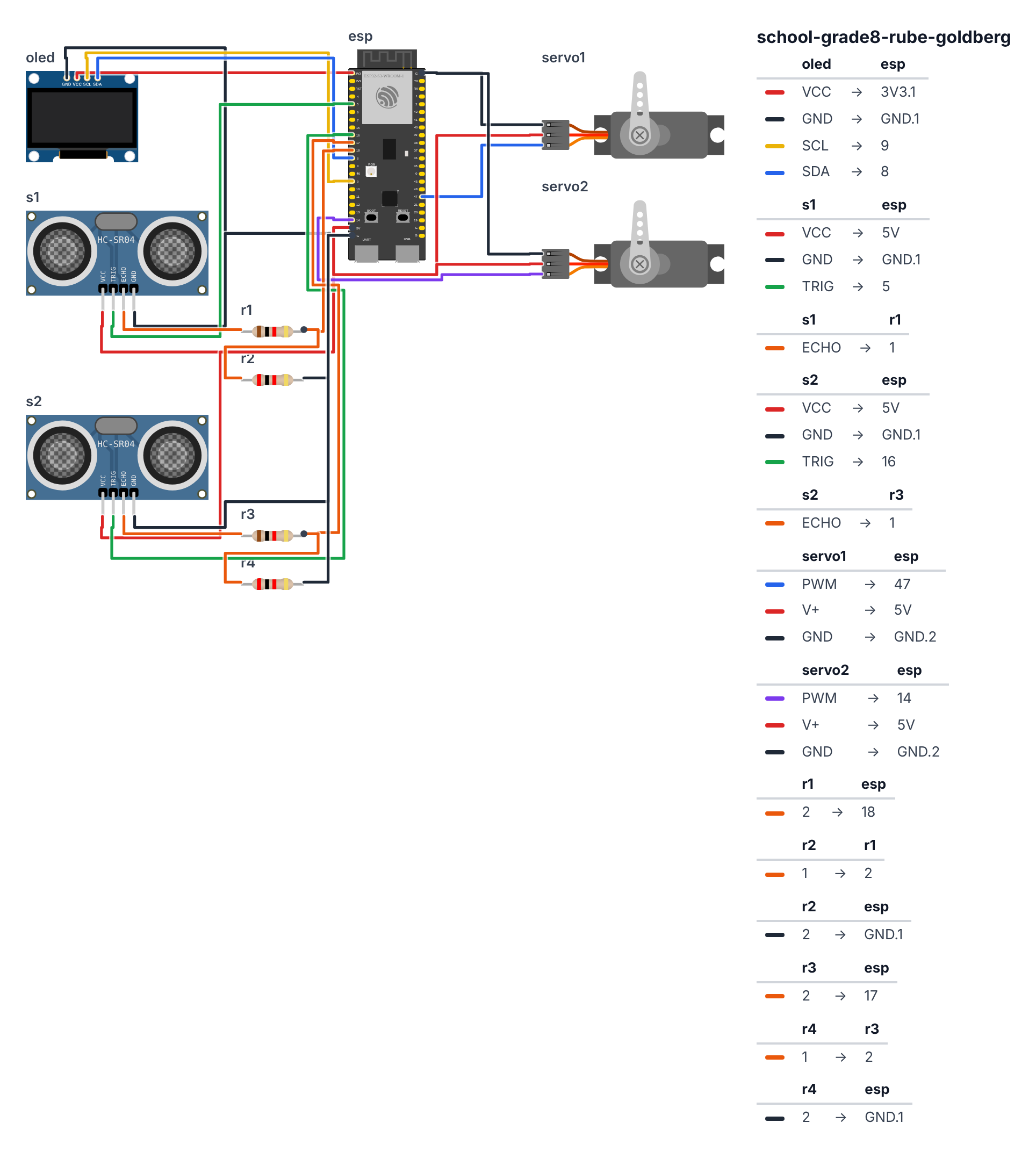
OLED Display (I2C):
- OLED VCC → board 3.3V — red wire
- OLED GND → board GND — black wire
- OLED SCL → board GPIO 9 (C6: GPIO 7) — yellow wire
- OLED SDA → board GPIO 8 (C6: GPIO 6) — blue wire
Ultrasonic Sensor 1 — Start trigger: 5. Sensor1 VCC → board 5V — red wire 6. Sensor1 GND → board GND — black wire 7. Sensor1 TRIG → board GPIO 5 (C6: GPIO 4) — green wire 8. Sensor1 ECHO → 1kΩ resistor → board GPIO 18 — orange wire 9. 2kΩ resistor from board GPIO 18 → board GND — so the 5V echo signal becomes a safe 3.3V
Ultrasonic Sensor 2 — Stage 2 detector: 10. Sensor2 VCC → board 5V — red wire 11. Sensor2 GND → board GND — black wire 12. Sensor2 TRIG → board GPIO 16 (C6: GPIO 20) — green wire 13. Sensor2 ECHO → 1kΩ resistor → board GPIO 17 (C6: GPIO 21) — orange wire 14. 2kΩ resistor from board GPIO 17 (C6: GPIO 21) → board GND — same trick as Sensor 1
Servo 1 — Release mechanism: 15. Servo1 signal → board GPIO 47 (C6: GPIO 5) — blue wire 16. Servo1 VCC → board 5V — red wire 17. Servo1 GND → board GND — black wire
Servo 2 — Final effect: 18. Servo2 signal → board GPIO 14 (C6: GPIO 3) — purple wire 19. Servo2 VCC → board 5V — red wire 20. Servo2 GND → board GND — black wire
Step 2: Flash the code
Time: ~25 minutes
Install Adafruit SSD1306, Adafruit GFX, and ESP32Servo libraries.
Think of this code as a physics timing machine with a memory — like a stopwatch that a race official uses, except it also controls two gates that open automatically. The machine has five “moods” it can be in: waiting to start, running and watching, stage 1 just fired, stage 2 just fired, and all done. Those five moods are tracked precisely — the machine never confuses “waiting” with “running.” Two ultrasonic sensors act as invisible tripwires: when something gets close enough, the tripwire fires. The ESP32 notes the exact millisecond it happened, calculates how long since the start, moves a servo to release the next stage, and keeps updating the display with the live timer.
// ========== CHOOSE YOUR BOARD ==========
// Uncomment the line for YOUR board:
#define BOARD_S3    // ESP32-S3-DevKitC-1
//#define BOARD_C6  // ESP32-C6-DevKitC-1
// ========================================

#ifdef BOARD_S3
  #define PIN_SDA    8
  #define PIN_SCL    9
  #define PIN_TRIG1  5
  #define PIN_ECHO1  18
  #define PIN_TRIG2  16
  #define PIN_ECHO2  17
  #define PIN_SERVO1 47
  #define PIN_SERVO2 14
  #define PIN_BTN    0
#endif
#ifdef BOARD_C6
  #define PIN_SDA    6
  #define PIN_SCL    7
  #define PIN_TRIG1  4
  #define PIN_ECHO1  18
  #define PIN_TRIG2  20
  #define PIN_ECHO2  21
  #define PIN_SERVO1 5
  #define PIN_SERVO2 3
  #define PIN_BTN    9
#endif

#include <Wire.h>
#include <Adafruit_SSD1306.h>
#include <ESP32Servo.h>

#define SCREEN_WIDTH 128
#define SCREEN_HEIGHT 64
Adafruit_SSD1306 display(SCREEN_WIDTH, SCREEN_HEIGHT, &Wire, -1);

#define TRIGGER_DIST_1 20
#define TRIGGER_DIST_2 15

Servo servo1;
Servo servo2;

#define SERVO_HOLD  10
#define SERVO_RELEASE 90

unsigned long machineStartTime = 0;
unsigned long stage1Time = 0;
unsigned long stage2Time = 0;
bool machineRunning = false;
bool stage1Complete = false;
bool stage2Complete = false;

enum MachineState {
  STANDBY,
  RUNNING,
  STAGE1_TRIGGERED,
  STAGE2_DETECTED,
  COMPLETE
};
MachineState state = STANDBY;

float measureDist(int trigPin, int echoPin) {
  digitalWrite(trigPin, LOW);
  delayMicroseconds(2);
  digitalWrite(trigPin, HIGH);
  delayMicroseconds(10);
  digitalWrite(trigPin, LOW);

  long duration = pulseIn(echoPin, HIGH, 25000);
  if (duration == 0) return 999;
  return (duration * 0.0343) / 2.0;
}

void updateDisplay() {
  display.clearDisplay();
  display.setTextColor(SSD1306_WHITE);
  display.setTextSize(1);

  switch (state) {
    case STANDBY:
      display.setCursor(0, 0);
      display.println("RUBE GOLDBERG");
      display.println("TIMING SYSTEM");
      display.println();
      display.println("Ready to run!");
      display.println("Press BOOT or");
      display.println("trigger sensor 1");
      break;

    case RUNNING:
    case STAGE1_TRIGGERED:
      {
        unsigned long elapsed = millis() - machineStartTime;
        display.setCursor(0, 0);
        display.print("RUN TIME: ");
        display.print(elapsed / 1000.0, 2);
        display.println("s");
        display.println();
        display.print("Step 1: ");
        if (stage1Complete) {
          display.print(stage1Time / 1000.0, 3); display.println("s");
        } else {
          display.println("waiting...");
        }
        display.print("Step 2: ");
        display.println("waiting...");
      }
      break;

    case STAGE2_DETECTED:
    case COMPLETE:
      display.setCursor(0, 0);
      display.println("--- RESULTS ---");
      display.print("Step 1: ");
      display.print(stage1Time / 1000.0, 3);
      display.println("s");
      display.print("Step 2: ");
      display.print(stage2Time / 1000.0, 3);
      display.println("s");
      display.print("Total: ");
      display.print((stage2Time) / 1000.0, 3);
      display.println("s");
      display.println("BOOT = reset");
      break;
  }

  display.display();
}

void startMachine() {
  machineStartTime = millis();
  stage1Complete = false;
  stage2Complete = false;
  state = RUNNING;
  updateDisplay();
}

void triggerStage1() {
  stage1Time = millis() - machineStartTime;
  stage1Complete = true;
  state = STAGE1_TRIGGERED;

  servo1.write(SERVO_RELEASE);
  delay(500);
  servo1.write(SERVO_HOLD);

  updateDisplay();
}

void detectStage2() {
  stage2Time = millis() - machineStartTime;
  stage2Complete = true;
  state = STAGE2_DETECTED;

  servo2.write(SERVO_RELEASE);
  delay(1000);
  servo2.write(SERVO_HOLD);

  state = COMPLETE;
  updateDisplay();
}

void resetMachine() {
  state = STANDBY;
  machineRunning = false;
  stage1Complete = false;
  stage2Complete = false;
  servo1.write(SERVO_HOLD);
  servo2.write(SERVO_HOLD);
  updateDisplay();
}

void setup() {
  Serial.begin(115200);
  Wire.begin(PIN_SDA, PIN_SCL);

  if (!display.begin(SSD1306_SWITCHCAPVCC, 0x3C)) {
    while (true);
  }

  pinMode(PIN_TRIG1, OUTPUT); pinMode(PIN_ECHO1, INPUT);
  pinMode(PIN_TRIG2, OUTPUT); pinMode(PIN_ECHO2, INPUT);

  servo1.attach(PIN_SERVO1);
  servo2.attach(PIN_SERVO2);
  servo1.write(SERVO_HOLD);
  servo2.write(SERVO_HOLD);

  pinMode(PIN_BTN, INPUT_PULLUP);

  updateDisplay();
}

bool lastBtn = HIGH;

void loop() {
  bool btn = digitalRead(PIN_BTN);
  if (lastBtn == HIGH && btn == LOW) {
    delay(50);
    if (state == STANDBY) {
      startMachine();
    } else if (state == COMPLETE) {
      resetMachine();
    }
  }
  lastBtn = btn;

  float dist1 = measureDist(PIN_TRIG1, PIN_ECHO1);
  float dist2 = measureDist(PIN_TRIG2, PIN_ECHO2);

  switch (state) {
    case STANDBY:
      if (dist1 < TRIGGER_DIST_1) {
        startMachine();
        delay(500);
      }
      break;

    case RUNNING:
      if (dist1 < TRIGGER_DIST_1) {
        triggerStage1();
        delay(200);
      }
      break;

    case STAGE1_TRIGGERED:
      if (dist2 < TRIGGER_DIST_2 && !stage2Complete) {
        detectStage2();
      }
      break;

    case STAGE2_DETECTED:
    case COMPLETE:
      break;
  }

  if (state == RUNNING || state == STAGE1_TRIGGERED) {
    updateDisplay();
  }

  delay(50);
}
Line-by-line: what every line does and why
Libraries and display setup
#include <Wire.h> — loads the I2C communication toolkit (the language the OLED uses).
#include <Adafruit_SSD1306.h> — loads the OLED drawing toolkit.
#include <ESP32Servo.h> — loads servo motor control. Without this library, telling a servo to move to 90° would require writing complicated timing pulses by hand.
#define SCREEN_WIDTH 128 and #define SCREEN_HEIGHT 64 — set the OLED pixel dimensions. #define is like writing a label on a sticky note: everywhere the code says SCREEN_WIDTH, the computer replaces it with 128 before running.
Adafruit_SSD1306 display(SCREEN_WIDTH, SCREEN_HEIGHT, &Wire, -1) — creates the display object. Think of it as building the tool before you use it. The &Wire means “use the I2C bus.” The -1 means “no reset pin needed.”
Sensor pin definitions
#define PIN_TRIG1 5 / #define PIN_ECHO1 18 — sensor 1 uses GPIO 5 to send a pulse and GPIO 18 to listen for the echo (C6: GPIO 4 and GPIO 18). #define PIN_TRIG2 16 / #define PIN_ECHO2 17 — sensor 2 uses GPIO 16 and GPIO 17 (C6: GPIO 20 and GPIO 21). Keeping these as #define names (instead of raw numbers) means if you rewire, you only change one line.
#define TRIGGER_DIST_1 20 — sensor 1 fires when something is closer than 20 cm. #define TRIGGER_DIST_2 15 — sensor 2 fires at 15 cm. These are the “tripwire distances.”
Servo setup
#define SERVO_HOLD 10 — 10° is the locked position (the servo arm blocks the mechanism). #define SERVO_RELEASE 90 — 90° swings the arm out of the way, releasing whatever is held.
Servo servo1; and Servo servo2; — create two servo objects. Think of each as a “remote control” for one servo motor.
Timing variables
unsigned long machineStartTime = 0; — will store the millisecond when the machine started. unsigned long is a whole number that can go up to about 49 days of milliseconds (4 billion ms), so it never overflows during a normal run.
unsigned long stage1Time = 0; — will store how many milliseconds elapsed between start and stage 1 firing. Same idea for stage2Time.
bool stage1Complete = false; — a bool (boolean) is a value that is only ever true or false. This flag tracks whether stage 1 has fired yet.
The state machine enum
enum MachineState {
  STANDBY,
  RUNNING,
  STAGE1_TRIGGERED,
  STAGE2_DETECTED,
  COMPLETE
};
MachineState state = STANDBY;
enum means “enumeration” — a list of named options. Think of it as the five positions on a dial: STANDBY / RUNNING / STAGE1_TRIGGERED / STAGE2_DETECTED / COMPLETE. state = STANDBY starts the dial at position 1. The rest of the code reads this dial and acts differently depending on where it points.
measureDist() — the sonar function
float measureDist(int trigPin, int echoPin) {
  digitalWrite(trigPin, LOW);
  delayMicroseconds(2);
  digitalWrite(trigPin, HIGH);
  delayMicroseconds(10);
  digitalWrite(trigPin, LOW);
  long duration = pulseIn(echoPin, HIGH, 25000);
  if (duration == 0) return 999;
  return (duration * 0.0343) / 2.0;
}
This is how bat sonar works in code form. The sensor sends out a pulse of ultrasound. The pulse bounces off objects and comes back. The time between sending and receiving tells you the distance.
digitalWrite(trigPin, LOW) then HIGH then LOW — creates the 10-microsecond starting pulse that tells the sensor “send your ping now.” delayMicroseconds(2) waits 2 millionths of a second — tiny, but the sensor needs it.
pulseIn(echoPin, HIGH, 25000) — listens on the echo pin and measures how long (in microseconds) the echo lasts. The 25000 is a timeout: if nothing echoes within 25,000 microseconds (~25ms), give up.
if (duration == 0) return 999; — if we timed out (nothing was detected), return 999 cm as a “nothing there” value. Any reasonable trigger distance (like 20 cm) is much less than 999, so this prevents false triggers.
return (duration * 0.0343) / 2.0; — converts time to distance. Sound travels at 343 meters per second = 0.0343 cm per microsecond. The echo travels to the object AND back, so we divide by 2 to get the one-way distance.
updateDisplay() — the screen drawing function
switch (state) — checks which position the “dial” is on and draws a different screen for each. case STANDBY: draws the welcome screen. case RUNNING: and case STAGE1_TRIGGERED: draw the live timer.
unsigned long elapsed = millis() - machineStartTime; — millis() returns how many milliseconds have passed since boot. Subtracting machineStartTime gives “milliseconds since this machine run started.” This is the standard pattern for timing without delay() — instead of waiting, you just subtract.
display.print(elapsed / 1000.0, 2) — divides by 1000 to convert milliseconds to seconds. The , 2 means “show 2 decimal places.” So 1234 ms becomes “1.23s.”
case STAGE2_DETECTED: and case COMPLETE: share the same results screen because both show final data. Two cases with one body of code is valid — the code “falls through” from one to the other.
startMachine(), triggerStage1(), detectStage2() — event handlers
startMachine(): saves millis() into machineStartTime (the clock starts ticking), sets both “complete” flags to false, moves the dial to RUNNING.
triggerStage1(): saves millis() - machineStartTime into stage1Time (how long since start). Moves servo1 to SERVO_RELEASE (90°), waits 500ms for the mechanism to drop, then moves back to SERVO_HOLD (10°) ready for next run. This is a blocking delay() — the code stops here for 0.5 seconds — which is fine because the mechanism needs that time to work.
detectStage2(): same idea — records stage2Time, fires servo2, waits 1000ms (the final effect needs a full second), then sets state = COMPLETE.
resetMachine(): sets state = STANDBY, sets both “complete” flags to false, moves both servos back to SERVO_HOLD, redraws the ready screen.
setup() — runs once at boot
Wire.begin(PIN_SDA, PIN_SCL); — starts I2C on GPIO 8 (SDA) and GPIO 9 (SCL) (C6: GPIO 6 and GPIO 7).
display.begin(SSD1306_SWITCHCAPVCC, 0x3C) — turns on the OLED at I2C address 0x3C. If this fails, while (true) hangs the program (so you know something is wrong instead of getting confusing behavior).
servo1.attach(PIN_SERVO1); / servo2.attach(PIN_SERVO2); — links each Servo object to its GPIO pin.
servo1.write(SERVO_HOLD) and servo2.write(SERVO_HOLD) — immediately move both servos to the “locked” position so the machine is ready from the very first second.
pinMode(PIN_BTN, INPUT_PULLUP); — sets GPIO 0 (C6: GPIO 9), the BOOT button on the ESP32, as an input with the internal pull-up resistor on. With a pull-up, the pin reads HIGH normally and LOW when pressed. This is the standard way to read a physical button without extra components.
loop() — runs forever
bool btn = digitalRead(PIN_BTN); — reads the BOOT button. HIGH = not pressed, LOW = pressed (because of the pull-up).
if (lastBtn == HIGH && btn == LOW) — detects the moment the button goes from not-pressed to pressed (the “falling edge”). Without this, holding the button down would trigger the action thousands of times per second. lastBtn = btn; at the end updates the memory for next time.
delay(50) inside the if-block — a 50ms pause before reading the button again. This is “debouncing” — physical buttons bounce electrically for a few milliseconds when pressed, and this pause skips past that noise.
float dist1 = measureDist(PIN_TRIG1, PIN_ECHO1); — pings sensor 1 and stores the result in dist1. Same for dist2.
The switch (state) in loop() is the core logic. Each case decides what to do with the sensor readings:
- In STANDBY: if something gets within 20 cm of sensor 1, auto-start.
- In RUNNING: if sensor 1 detects something (the machine’s first stage passing by), call
triggerStage1(). - In STAGE1_TRIGGERED: watch sensor 2; when something passes, call
detectStage2(). - In COMPLETE or STAGE2_DETECTED: do nothing (wait for BOOT button to reset).
if (state == RUNNING || state == STAGE1_TRIGGERED) { updateDisplay(); } — only updates the live timer when the machine is actually running. In STANDBY or COMPLETE, the display doesn’t need to refresh every 50ms.
delay(50) at the bottom — the main loop runs ~20 times per second. This is fast enough to catch flying objects (a ball rolling at 1 m/s moves 5 cm between checks — well within the 20 cm trigger zone).
The whole thing in one sentence: Two ultrasonic tripwires detect when objects pass them, record exact timestamps, and fire servos to release the next stage — all while a state machine tracks whether the run is waiting, active, or complete.
First thing to try: Press BOOT to start the timer, then slowly wave your hand in front of Sensor 1 — you should hear the servo click and see “Step 1: 0.XXXs” appear on the OLED.
Check: Press BOOT button to start the timer. Walk something in front of Sensor 1 — it should log Stage 1 time and move Servo 1. Walk something in front of Sensor 2 — it should log Stage 2 time, trigger Servo 2, and display final results. Press BOOT again to reset.
Step 3: Calibrate sensor distances
Test each sensor’s trigger distance before installing in your machine:
// Temporary test — add to loop() to find good trigger distances
Serial.print("S1: "); Serial.print(measureDist(PIN_TRIG1, PIN_ECHO1));
Serial.print("cm  S2: "); Serial.print(measureDist(PIN_TRIG2, PIN_ECHO2));
Serial.println("cm");
Adjust TRIGGER_DIST_1 and TRIGGER_DIST_2 in the code to match where you position the sensors relative to the objects passing them.
What just happened
Physics concepts you measured:
- Energy transfer — each step transfers energy from one form to another. The timing data shows which transfers are fast (efficient) and which are slow.
- Average speed — time + distance = speed. If you know how far a ball rolled between sensors, divide that distance by the step time to get the ball’s average speed in cm/s.
- Newton’s laws — every step involves forces, inertia, and acceleration. The servo provides an applied force. The ball’s speed shows its inertia.
- Repeatability — run your machine 3 times. Do the times match? Variation between runs shows which steps are “noisy” (unpredictable) vs. reliable.
Curriculum alignment: NGSS MS-PS3-1 (Construct and interpret graphical displays of data to describe the relationships of kinetic energy to the mass and speed of an object). MS-PS3-2 (Develop a model to describe that when the arrangement of objects interacting at a distance changes, different amounts of potential energy are stored in the system).
Presentation tip: Show your timing data table. Run the machine live 3 times and compare the times. If they vary, ask your class: “Why did Step 1 take longer in run 2?” This is real experimental analysis — not just watching a chain reaction.
Level Up
Calculate velocity: If you measure the distance between sensors (in cm), divide it by the step time (in seconds) to calculate average ball speed. Add this calculation to the code and display it.
Add more stages: Each additional ultrasonic sensor adds another timed stage. Three sensors = two time intervals = two speed measurements.
Energy efficiency: If you can measure the height a ball drops between stages, calculate potential energy (mgh) before and kinetic energy (½mv²) after. The difference is energy lost to friction and air resistance.
★★ You completed: Grade 8 Rube Goldberg Machine!
Troubleshooting
| Problem | Fix |
|---|---|
| Sensor triggers too easily / not at all | Adjust TRIGGER_DIST_1 and TRIGGER_DIST_2 based on your actual sensor positions. |
| Servo moves to wrong position | SERVO_HOLD = 10°, SERVO_RELEASE = 90°. Adjust these based on your physical mechanism. |
| Machine starts on its own | Something is within 20cm of Sensor 1. Adjust trigger distance or move the sensor. |
| Only one sensor works | GPIO 5/18 = Sensor 1, GPIO 16/17 = Sensor 2 (C6: GPIO 4/18 and GPIO 20/21). Don’t mix TRIG/ECHO pins between sensors. |
| Timing seems too fast or too slow | The code samples every 50ms. For very fast machines, reduce to 10ms for higher resolution. |