Parent info
Parts you need
Affiliate links — we may earn a small commission
Try this circuit in your browser!
Run the code, press the buttons and watch what happens — before you buy any parts. No account needed.
Open in Simulator →The same hardware inside a $500 power meter. For $41.
Imagine this: you open the Garmin Connect app on your phone during your ride. It shows 187 watts. That number came from a strain gauge bonded to your crank arm, an HX711 amplifier reading microvolts of resistance change, and your ESP32 broadcasting it as standard BLE Cycling Power Service — the same protocol a $500 Quarq uses.
You built that. For $41. And you understand every equation that turns flex on a metal arm into watts.
Total: ~$41 | Time: ~5 hours | Difficulty: ●●●●○
This is an advanced project. The electronics are straightforward. The hard part is bonding the strain gauge to the crank arm — it requires careful surface prep and 24 hours of cure time. Read the whole guide before buying parts.
What you’ll need
| Part | What it does | Price |
|---|---|---|
| ESP32 Dev Board | Brain: reads HX711, measures cadence, broadcasts BLE. | ~$12 |
| HX711 Load Cell Amplifier | 24-bit ADC with 128× gain — reads the tiny strain gauge signal. | ~$4 |
| Strain Gauge (350Ω, 3mm gauge length) | Foil that changes resistance when the crank arm flexes. Order a pack of 10. | ~$8 |
| Hall Effect Sensor (A3144) | Detects cadence — one pulse per pedal revolution. | ~$2 |
| LiPo 250mAh + TP4056 | Fits inside a small epoxy-potted enclosure on the crank. | ~$8 |
| Loctite 401 adhesive | The only correct adhesive for bonding strain gauges to metal. | ~$6 |
| Small neodymium magnet | On the pedal/crank for cadence detection. | ~$1 |
Total: ~$41
You also need: Arduino IDE, USB cable, acetone for surface prep, 220-grit sandpaper, and patience for the 24-hour cure.
How it works (60 seconds)
Power in watts = Force × Velocity. That’s the only equation you need.
Force comes from the strain gauge. When you push down on the pedal, the crank arm bends slightly. A strain gauge is a thin metal foil — 0.3mm thick — whose electrical resistance changes as it bends. The change is tiny: 0.1% under a typical load, which is microvolts. The HX711 amplifies that signal 128× and sends a 24-bit digital number to the ESP32.
Velocity comes from the hall sensor. One magnet on the crank arm fires one pulse per revolution. The ESP32 measures the time between pulses and calculates cadence in RPM. Velocity = 2 × π × crank length × (RPM / 60).
Multiply force by velocity: watts. Your Garmin or phone receives those watts over BLE using the standard Cycling Power Service (UUID 0x1818) — the same protocol every commercial power meter uses.
Step 0: Bond the strain gauge
Time: ~30 minutes active + 24 hours cure
This is the hardest and most critical step. Do it first — the rest of the build waits for the cure.
Surface preparation:
- Clean the crank arm surface with acetone on a lint-free cloth. Wipe until no residue comes off.
- Rough the surface lightly with 220-grit sandpaper — just enough to remove the anodizing in the bonding area (about 15mm × 15mm).
- Clean again with acetone. Do not touch the cleaned area with bare fingers.
Gauge placement:
- Position the strain gauge perpendicular to the crank arm axis (the gauge grid lines run across the arm, not along it). This orientation maximizes the signal from bending forces.
- Mark the center of the bonding spot with a fine marker while the gauge is in position. Remove the gauge.
Bonding:
- Apply a single small drop of Loctite 401 to the gauge backing.
- Align the gauge center mark with your marked spot. Press firmly.
- Hold with your thumb for 60 seconds — steady pressure, no movement.
- Place a small weight (a coin works) on top and leave for 24 hours.
Check: After curing, try to lift the gauge edge gently with a fingernail. It should be completely immovable. If it peels, the surface wasn’t clean enough. Order another gauge from your pack of 10 and try again on a fresh spot.
Pro tip: For double the signal and better temperature stability, bond two gauges — one on top of the crank arm, one on the bottom, in a half-bridge configuration. Connect them to HX711 A+ and A- (instead of one gauge to each). This doubles the signal and cancels temperature drift.
Step 1: Wire it up
Time: ~15 minutes
Which board? This guide is wired for a classic ESP32 DevKit — the “ESP32 Dev Board” in the parts list. Building it on an ESP32-S3 or ESP32-C6 instead? Pick your board at the top of the code and use the pins in brackets.
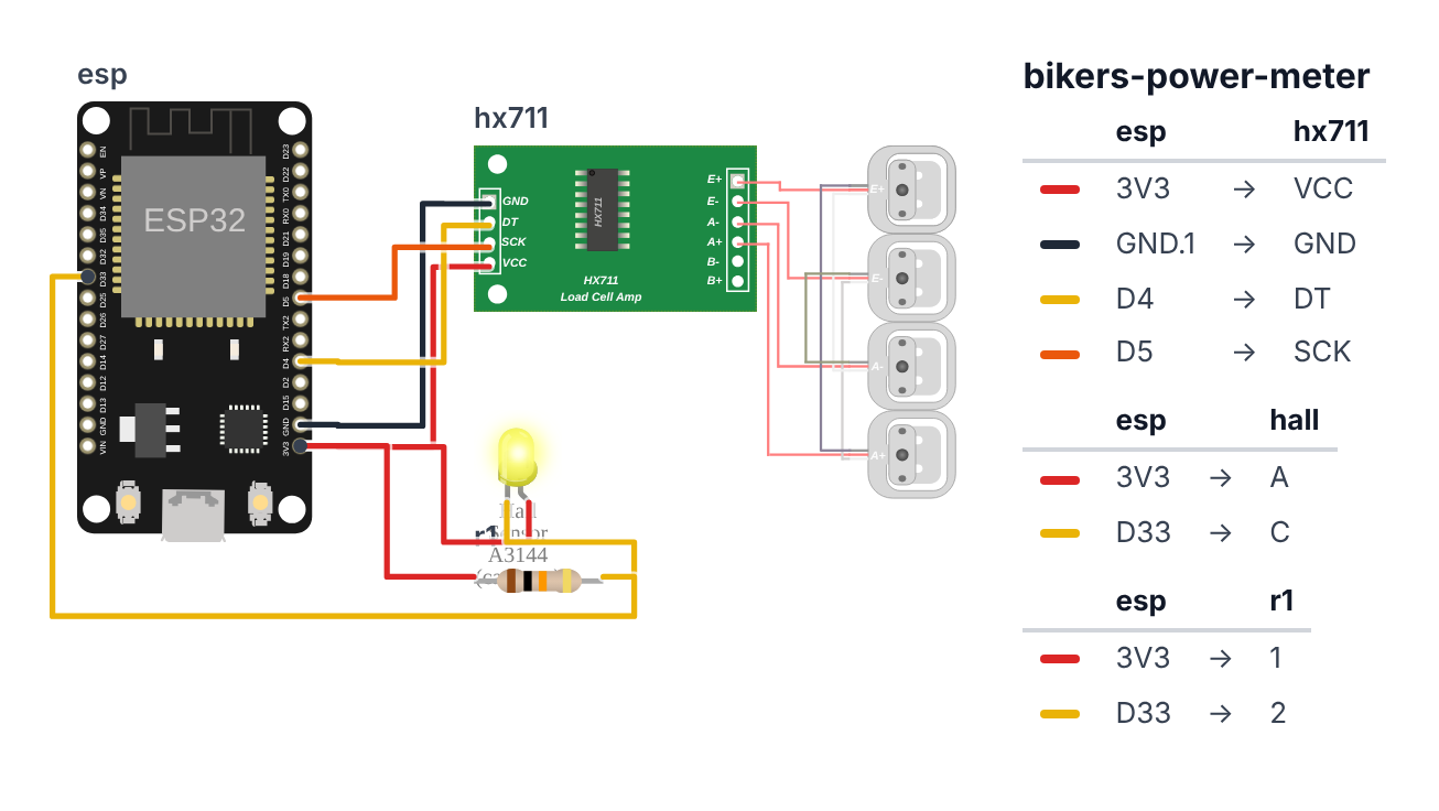
HX711 Amplifier — 4 wires:
- HX711 VCC → ESP32 3.3V — red wire
- HX711 GND → ESP32 GND — black wire
- HX711 DT (data) → ESP32 GPIO4 (S3: GPIO4, C6: GPIO0) — yellow wire
- HX711 SCK (clock) → ESP32 GPIO5 (S3: GPIO5, C6: GPIO19) — orange wire
Strain Gauge → HX711 — 4 wires: 5. Gauge excitation wire (red) → HX711 E+ 6. Gauge excitation wire (black) → HX711 E- 7. Gauge signal wire (green/white) → HX711 A+ 8. Gauge signal wire (white/green) → HX711 A-
Hall Effect Sensor (cadence) — 3 wires: 9. Hall VCC → ESP32 3.3V — red wire 10. Hall GND → ESP32 GND — black wire 11. Hall OUT → ESP32 GPIO33 (S3: GPIO2, C6: GPIO10) — yellow wire 12. 10kΩ resistor between GPIO33 (S3: GPIO2, C6: GPIO10) and 3.3V (pull-up)
ESP32            HX711
  3.3V ─────────── VCC
  GND  ─────────── GND
  GPIO4 ─────────── DT  (data)
  GPIO5 ─────────── SCK (clock)

HX711            Strain Gauge (half-bridge)
  E+ ─────────── + excitation wire (red)
  E- ─────────── - excitation wire (black)
  A+ ─────────── + signal wire (green/white)
  A- ─────────── - signal wire (white/green)

ESP32            Hall Sensor (cadence)
  3.3V ─────────── VCC
  GND  ─────────── GND
  GPIO33 ─────────── OUT (+ 10kΩ pullup to 3.3V)
Check: Route the strain gauge wires carefully along the crank arm surface using kapton tape — never across a moving joint. Leave enough slack for the crank to rotate without straining the wires.
Step 2: Flash the code
Time: ~10 minutes
- Install libraries (Sketch > Manage Libraries):
HX711 Arduino Libraryby Bogdan NeculaNimBLE-Arduinoby h2zero (version 1.4.x or later)
The big picture first. This program measures how hard you push the pedals and broadcasts that as watts over Bluetooth — the same standard protocol a $500 Quarq power meter uses.
- A strain gauge bonded to your crank arm changes electrical resistance when the crank flexes under load. The change is tiny — the HX711 amplifier boosts it 128 times and converts it to a digital number.
- A hall effect sensor counts crank revolutions. One magnet on the crank fires one pulse per revolution. The ESP32 measures the time between pulses to calculate cadence in RPM.
- The power formula is just physics: Power (watts) = Force (newtons) × Velocity (meters per second). The strain gauge gives force. Cadence and crank length give velocity.
- The ESP32 acts as a BLE server — it advertises the standard Cycling Power Service (UUID 0x1818). Any Garmin, Wahoo, or phone can connect and read watts, just like a commercial power meter.
// ========== CHOOSE YOUR BOARD ==========
// Uncomment the line for YOUR board:
#define BOARD_ESP32  // classic ESP32 DevKit (ESP32-WROOM-32)
//#define BOARD_S3    // ESP32-S3-DevKitC-1
//#define BOARD_C6  // ESP32-C6-DevKitC-1
// ========================================

#ifdef BOARD_ESP32
  #define PIN_HX711_DT         4
  #define PIN_HX711_SCK        5
  #define PIN_HALL             33
#endif
#ifdef BOARD_S3
  #define PIN_HX711_DT         4
  #define PIN_HX711_SCK        5
  #define PIN_HALL             2
#endif
#ifdef BOARD_C6
  #define PIN_HX711_DT         0
  #define PIN_HX711_SCK        19
  #define PIN_HALL             10
#endif

#include <Arduino.h>
#include <HX711.h>
#include <NimBLEDevice.h>
#include <NimBLEServer.h>
#include <NimBLEUtils.h>

#define HX711_DT_PIN  PIN_HX711_DT
#define HX711_SCK_PIN PIN_HX711_SCK
HX711 scale;

#define HALL_PIN       PIN_HALL
#define CRANK_LENGTH_M 0.1725f

volatile unsigned long lastCadencePulse = 0;
volatile unsigned long cadenceDeltaUs   = 0;
volatile bool          newCadencePulse  = false;

float calibrationFactor = 420.0f;
float zeroOffset        = 0.0f;

#define CYCLING_POWER_SERVICE_UUID "1818"
#define CYCLING_POWER_CHAR_UUID    "2A63"
#define CYCLING_POWER_FEATURE_UUID "2A65"

NimBLEServer*         pServer    = nullptr;
NimBLECharacteristic* pPowerChar = nullptr;
bool                  bleConnected = false;

float powerReadings[8] = {0};
int   pwrIdx           = 0;
float avgPowerW        = 0.0f;
float peakPowerW       = 0.0f;
int   cadenceRPM       = 0;

void IRAM_ATTR cadenceISR() {
  unsigned long now = micros();
  if (now - lastCadencePulse > 100000) {
    cadenceDeltaUs   = now - lastCadencePulse;
    lastCadencePulse = now;
    newCadencePulse  = true;
  }
}

class ServerCallbacks : public NimBLEServerCallbacks {
  void onConnect(NimBLEServer* pSvr, NimBLEConnInfo& connInfo) override {
    bleConnected = true;
    Serial.println("Garmin/phone connected.");
  }
  void onDisconnect(NimBLEServer* pSvr, NimBLEConnInfo& connInfo, int reason) override {
    bleConnected = false;
    NimBLEDevice::startAdvertising();
  }
};

void sendPowerBLE(int16_t powerW, uint16_t cadenceRpm) {
  if (!pPowerChar) return;
  uint8_t buf[4];
  uint16_t flags = 0x0000;
  buf[0] = flags & 0xFF;
  buf[1] = (flags >> 8) & 0xFF;
  buf[2] = (uint8_t)(powerW & 0xFF);
  buf[3] = (uint8_t)((powerW >> 8) & 0xFF);
  pPowerChar->setValue(buf, 4);
  pPowerChar->notify();
}

void setup() {
  Serial.begin(115200);

  scale.begin(HX711_DT_PIN, HX711_SCK_PIN);
  scale.set_scale(calibrationFactor);
  delay(500);
  zeroOffset = scale.read_average(10);
  scale.set_offset(zeroOffset);
  Serial.println("HX711 tared. Apply a known weight to calibrate.");
  Serial.println("Adjust calibrationFactor until scale reads correct grams.");

  pinMode(HALL_PIN, INPUT_PULLUP);
  attachInterrupt(digitalPinToInterrupt(HALL_PIN), cadenceISR, FALLING);

  NimBLEDevice::init("BuildCool PowerMeter");
  pServer = NimBLEDevice::createServer();
  pServer->setCallbacks(new ServerCallbacks());

  NimBLEService* pService = pServer->createService(CYCLING_POWER_SERVICE_UUID);

  pPowerChar = pService->createCharacteristic(CYCLING_POWER_CHAR_UUID, NIMBLE_PROPERTY::NOTIFY);

  NimBLECharacteristic* pFeatureChar =
    pService->createCharacteristic(CYCLING_POWER_FEATURE_UUID, NIMBLE_PROPERTY::READ);
  uint32_t features = 0;
  pFeatureChar->setValue((uint8_t*)&features, 4);

  pService->start();

  NimBLEAdvertising* pAdv = NimBLEDevice::getAdvertising();
  pAdv->addServiceUUID(CYCLING_POWER_SERVICE_UUID);
  pAdv->setScanResponseData(true);
  NimBLEDevice::startAdvertising();
  Serial.println("BLE advertising: 'BuildCool PowerMeter'");
}

void loop() {
  if (scale.is_ready()) {
    float forceN = scale.get_units(1) * 9.81f / 1000.0f;
    forceN = max(0.0f, forceN);

    if (newCadencePulse) {
      newCadencePulse = false;
      if (cadenceDeltaUs > 0) {
        cadenceRPM = (int)(60000000.0f / cadenceDeltaUs);
        cadenceRPM = constrain(cadenceRPM, 0, 200);
      }
    }
    if (micros() - lastCadencePulse > 3000000UL) cadenceRPM = 0;

    float crankVelocity = 2.0f * PI * CRANK_LENGTH_M * (cadenceRPM / 60.0f);
    float instantPowerW = forceN * crankVelocity;

    powerReadings[pwrIdx % 8] = instantPowerW;
    pwrIdx++;
    float sum = 0;
    for (int i = 0; i < 8; i++) sum += powerReadings[i];
    avgPowerW = sum / 8.0f;
    if (avgPowerW > peakPowerW) peakPowerW = avgPowerW;

    Serial.printf("Force: %.1fN  Cadence: %drpm  Power: %.0fW  Avg: %.0fW  Peak: %.0fW\n",
      forceN, cadenceRPM, instantPowerW, avgPowerW, peakPowerW);

    sendPowerBLE((int16_t)avgPowerW, (uint16_t)cadenceRPM);
  }

  delay(100);
}
Line-by-line: what every line does and why
Lines 1–5: Libraries
#include <HX711.h>
#include <NimBLEDevice.h>
#include <NimBLEServer.h>
HX711 handles communication with the 24-bit amplifier chip that reads the strain gauge. NimBLEDevice and NimBLEServer set up the ESP32 as a BLE server that other devices can connect to — the opposite role from the heart rate display project, where the ESP32 was the client.
Calibration variables
float calibrationFactor = 420.0f;
float zeroOffset        = 0.0f;
calibrationFactor converts raw HX711 counts to grams. Every strain gauge installation is slightly different — the factor is tuned by hanging a known weight and adjusting until the reading matches. zeroOffset is set during taring — reading 10 samples with no force and storing the average. All future readings subtract this offset so the crank’s own weight doesn’t count.
The BLE UUIDs
#define CYCLING_POWER_SERVICE_UUID "1818"
#define CYCLING_POWER_CHAR_UUID    "2A63"
#define CYCLING_POWER_FEATURE_UUID "2A65"
These three codes are defined by the Bluetooth SIG — the organization that sets Bluetooth standards. 1818 is the Cycling Power Service. 2A63 is the Power Measurement value. 2A65 is mandatory metadata about which features the power meter supports. Any Garmin, Wahoo, or cycling app that can read a power meter looks for exactly these UUIDs.
cadenceISR(): counting crank revolutions
void IRAM_ATTR cadenceISR() {
  unsigned long now = micros();
  if (now - lastCadencePulse > 100000) {
    cadenceDeltaUs   = now - lastCadencePulse;
    lastCadencePulse = now;
    newCadencePulse  = true;
  }
}
IRAM_ATTR stores this function in fast RAM for interrupt speed. Every time the magnet on the crank passes the hall sensor, this fires. cadenceDeltaUs stores the time between pulses in microseconds. The 100ms debounce filters out any electrical noise from the magnet passing. newCadencePulse = true flags loop() that fresh data is ready.
sendPowerBLE(): packing watts into Bluetooth format
buf[0] = flags & 0xFF;
buf[1] = (flags >> 8) & 0xFF;
buf[2] = (uint8_t)(powerW & 0xFF);
buf[3] = (uint8_t)((powerW >> 8) & 0xFF);
pPowerChar->setValue(buf, 4);
pPowerChar->notify();
The Bluetooth SIG specifies the exact byte format for Cycling Power data. Bytes 0 and 1 are “flags” — feature bits. Bytes 2 and 3 are the power value in watts as a 16-bit integer. & 0xFF extracts the lower 8 bits (the “low byte”). >> 8 shifts right by 8 bits to get the upper 8 bits (the “high byte”). notify() pushes this 4-byte packet to every connected Garmin or phone.
setup(): taring the scale and starting BLE
scale.read_average(10);
scale.set_offset(zeroOffset);
read_average(10) reads 10 samples and returns the average — with no force applied, this is the crank arm’s own weight. set_offset tells the library “this value means zero force.” Every future reading subtracts it, so the scale only measures the force you apply with your legs.
pPowerChar = pService->createCharacteristic(CYCLING_POWER_CHAR_UUID, NIMBLE_PROPERTY::NOTIFY);NIMBLE_PROPERTY::NOTIFY means: Garmin/phone can subscribe, and the ESP32 pushes updates automatically. Clients don’t need to ask — they register once and receive data every time notify() is called.
loop(): the power formula
float forceN = scale.get_units(1) * 9.81f / 1000.0f;get_units(1) returns grams after calibration. Multiply by 9.81 to convert gram-force to Newtons (the physics unit of force). Divide by 1000 because g * 9.81 / 1000 = N (since 1 Newton = 1 kg × 1 m/s², and 1 kg = 1000g).
cadenceRPM = (int)(60000000.0f / cadenceDeltaUs);60,000,000 microseconds = 60 seconds = 1 minute. Divide 1 minute by the time for one revolution to get revolutions per minute. At 80 RPM, one revolution takes 750,000 µs. 60,000,000 / 750,000 = 80 RPM.
float crankVelocity = 2.0f * PI * CRANK_LENGTH_M * (cadenceRPM / 60.0f);
float instantPowerW = forceN * crankVelocity;
2 × π × crank_length is the circumference of the circle the crank tip travels. Multiply by RPM/60 (revolutions per second) to get velocity in m/s. Then Power = Force × Velocity. At 80 RPM with 172.5mm cranks and 100N of force: 2 × 3.14 × 0.1725 × (80/60) × 100 = 144 watts.
The whole thing in one sentence
Every 100ms the strain gauge reads force, the hall sensor provides cadence, and the power formula multiplies them — then the result is packed into the standard BLE format and pushed to any connected Garmin or phone.
First thing to try: after uploading, open Serial Monitor and push down on the crank arm by hand while a magnet passes the hall sensor. You should see Force, Cadence, and Power values updating in real time.
Check: Open Serial Monitor. You should see “HX711 tared.” Move the crank arm by hand — the force reading should change. The power will be 0 until you spin the crank (cadence > 0).
Step 3: Calibrate with a known weight
Time: ~20 minutes
The calibrationFactor converts raw HX711 counts into grams. You need to tune it.
- Hang the bike so the crank is horizontal.
- Flash the code and open Serial Monitor.
- The code auto-tares on boot — force should read ~0.
- Hang a known weight from the pedal (a 5kg dumbbell, a bag of water bottles you’ve weighed).
- Read the force value in Serial Monitor. It should show 5000 (grams).
- If it reads 6500, your
calibrationFactoris too low — increase it (try 550). - If it reads 3500, decrease
calibrationFactor(try 300). - Repeat until Serial Monitor shows within 50g of your actual weight.
Check: Remove the weight — force should return to ~0. Apply the weight again — should read the same value. Consistent readings mean your gauge is bonded correctly.
Step 4: Test the BLE output
- Download nRF Toolbox or Cyclemeter on your phone. Both can connect to the Cycling Power Service UUID.
- Power on your ESP32 and open the app.
- Scan for Bluetooth devices — look for “BuildCool PowerMeter.”
- Connect. Spin the pedals by hand while watching the watts on your phone.
- Push harder — power should increase. Spin faster — power should increase.
Check: The power reading responds to both force (harder push = more watts) and cadence (faster spin = more watts). If only one changes the reading, check that the hall sensor and strain gauge are both connected.
What just happened (what you learned)
-
Strain gauges and the Wheatstone bridge — a strain gauge is a thin metal foil whose electrical resistance changes when it bends. A single gauge changes resistance by ~0.1% under load — far too small for a standard ADC. The HX711 is a 24-bit ADC with built-in 128× gain. The 4-wire connection (E+, E-, A+, A-) forms a Wheatstone bridge — a circuit that amplifies the tiny resistance difference while canceling temperature drift.
-
Power = Force × Velocity — this is the fundamental equation. At 80 RPM with 172.5mm cranks, the crank tip moves at
2 × π × 0.1725 × (80/60) = 1.44 m/s. Apply 100N of force:100 × 1.44 = 144 watts. This is the same calculation every commercial power meter uses. -
BLE GATT server — in the heart rate display project, the ESP32 was a client that connected to an existing device. Here, the ESP32 is the server — it advertises a service and waits for a Garmin or phone to connect.
NimBLEDevice::createServer()creates the server. Advertising restarts automatically on disconnect. -
Taring and zero offset —
scale.set_offset(zeroOffset)tells the HX711 library: “this value is zero force.” All subsequent readings are relative to this zero. Taring removes the crank arm’s own weight. If you remount the sensor or ride in a different temperature, tare again — thermal expansion shifts the zero point.
Level Up
Add an OLED display: Add an SSD1306 OLED (or use the Heltec board from the Trail Logger project). Show live watts, cadence RPM, and peak watts. Removes the dependency on a Garmin for during-ride feedback.
Left/right power balance: Use two strain gauges and two HX711 chips — one on each crank arm. Calculate leftPowerW and rightPowerW separately. Add the balance flag to the BLE packet (bit 3 = 1 in the flags byte). This is professional-grade data that commercial meters charge $600+ for.
Weatherproof with epoxy potting: The HX711 and ESP32 live in a small enclosure. Drill cable entry holes, insert wires, fill with two-part epoxy resin. Vibration-resistant and fully waterproof. Mount with M3 bolts and threadlocker. Calibrate again after any temperature change greater than 15°C — thermal expansion shifts the zero offset.
Troubleshooting
| Problem | Fix |
|---|---|
| HX711 reads random garbage | Check DT → GPIO4, SCK → GPIO5 (S3: DT → GPIO4, SCK → GPIO5; C6: DT → GPIO0, SCK → GPIO19). Use 3.3V for HX711 VCC (not 5V on some boards that can’t supply 5V). |
| Force always reads 0 even with weight | Gauge may not be bonded — try to flex the gauge wire gently. If nothing changes, re-bond with fresh Loctite 401. |
| Power is always 0 | Power = Force × Velocity. Check that cadence is > 0 in Serial Monitor. Spin the crank while waving a magnet past the hall sensor. |
| BLE device not found on Garmin | Garmin requires the Cycling Power Service UUID 0x1818. Confirm the service is created with that UUID exactly. |
| Force reading drifts over time | Temperature compensation — if riding in cold weather, tare the scale before each ride. Two-gauge half-bridge configuration dramatically reduces thermal drift. |
| Calibration is unstable | Ensure the crank is locked in place during calibration (bike in a stand). Any movement adds force to the reading. |