Coming Soon
This project is being tested and polished. Check back soon!
Parent info
Parts you need
Affiliate links — we may earn a small commission
5 ESP32 + 3D Printer Projects That Look Like Real Products
Most maker projects die on a breadboard. The wires go everywhere, the components fall out, and the whole thing sits in a drawer after a week. The fix is simple: put it in a case.
A 3D-printed enclosure transforms your project from “experiment” to “gadget.” It protects the electronics, makes buttons and screens easy to reach, and — most importantly — makes you proud to show it off.
These five projects each combine an ESP32 with a custom-printed case. You do not need to be a 3D design expert. Every project here uses TinkerCAD, which is free, runs in your browser, and takes about 20 minutes to learn. You will find existing STL files online to start from, then tweak them to fit your parts exactly.
What You Need for All Projects
| Part | Price | Link |
|---|---|---|
| ESP32-S3 Dev Board | ~$12 | Buy |
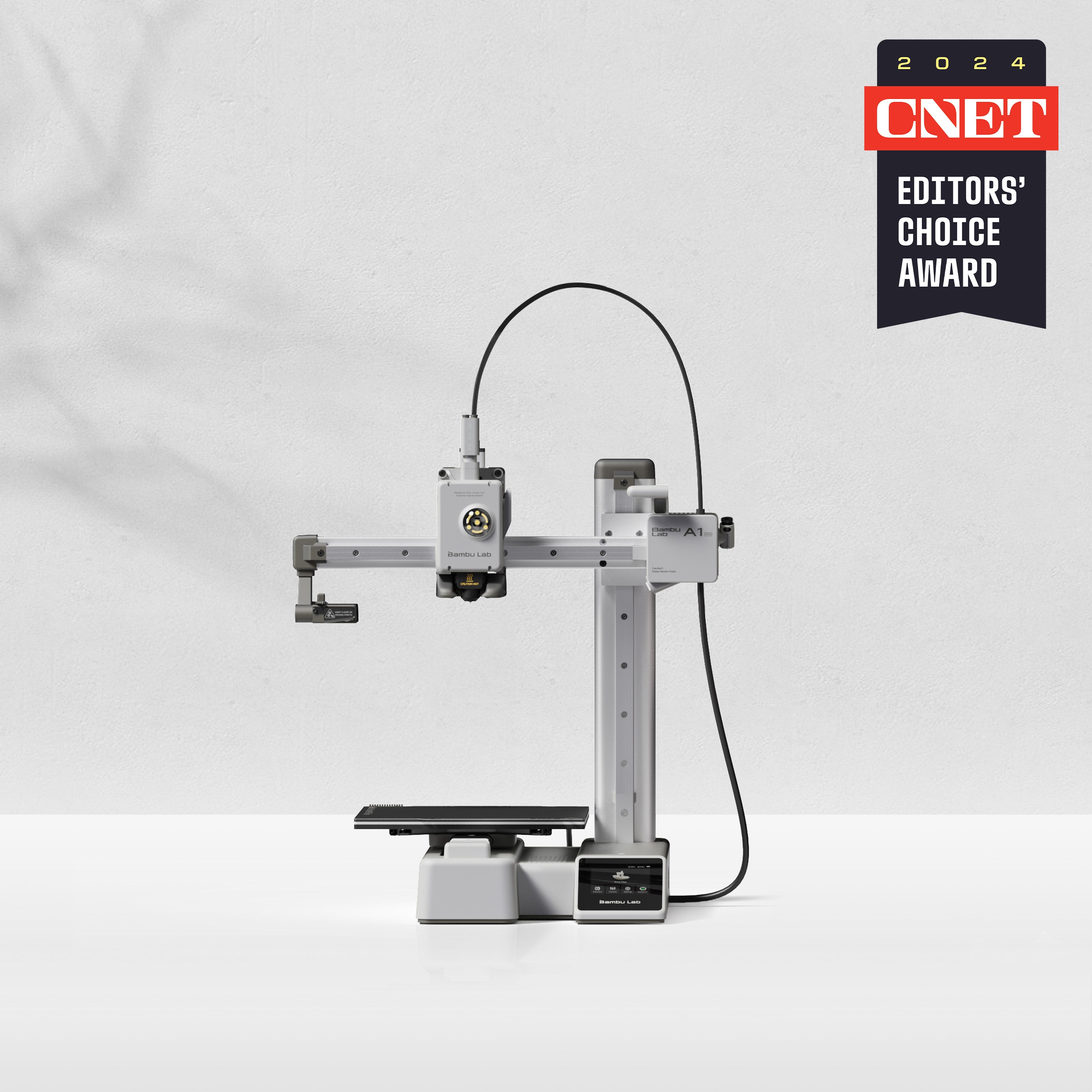
| 3D Printer (Bambu Lab A1 Mini or similar FDM) | ~$200 | Buy |
 | PLA Filament 1kg (any brand, white or black) | ~$15 | Buy |
No 3D printer? Check if your school has one, or find a local makerspace at makerspaces.com. Many public libraries also have printers you can book for free.
Universal Print Settings
Use these settings for all five projects unless noted otherwise:
- Material: PLA (easiest to print, available everywhere)
- Layer height: 0.2mm (good balance of speed and detail)
- Infill: 20% (light enough to print fast, strong enough for electronics)
- Supports: Only where noted per project
- Print speed: Default for your slicer (45–60mm/s works well)
- Bed temp: 60°C, Nozzle: 215°C
Project 1: M5Stack Cardputer Wrist Mount
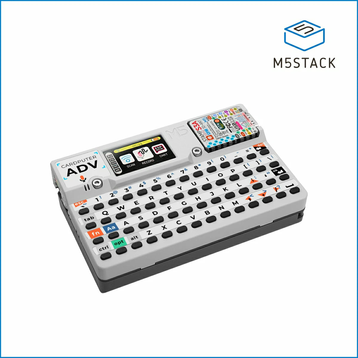
What it is: The M5Stack Cardputer is a credit-card-sized computer with a tiny keyboard and screen built in. It runs MicroPython or Arduino code and can connect to WiFi, run a terminal, or even send SMS. It is already impressive on a desk — but attach it to your wrist and it becomes a wearable pocket computer.
What You Need
- M5Stack Cardputer (~$30)
- 2x M3 screws (10mm)
- Watch strap or nylon webbing (25mm wide)
Find the STL
Search Printables.com for M5Stack Cardputer wrist mount. Several community designs exist — look for one with a four-screw attachment pattern and a slot for a standard watch strap. Alternatively, search Thingiverse for Cardputer arm mount.
Customize in TinkerCAD
- Go to tinkercad.com and create a free account.
- Import the downloaded STL (click Import in the top right).
- To widen the strap slot: select the slot cutout shape, change its width dimension to match your strap exactly.
- To add your name or a logo: use the Text shape tool, set height to 1mm, and place it on the back panel. Export as STL when done.
Assembly Notes
Print the mount flat-side down, no supports needed. Slide the strap through the slots before screwing the Cardputer in — you cannot reverse this order. Tighten the M3 screws finger-tight only. Over-tightening will crack the PLA.
Level Up
Flash the Cardputer with a custom MicroPython script that shows your name, current time (synced over WiFi), and a mini game you can play while wearing it.
Project 2: DIY Smartwatch Case
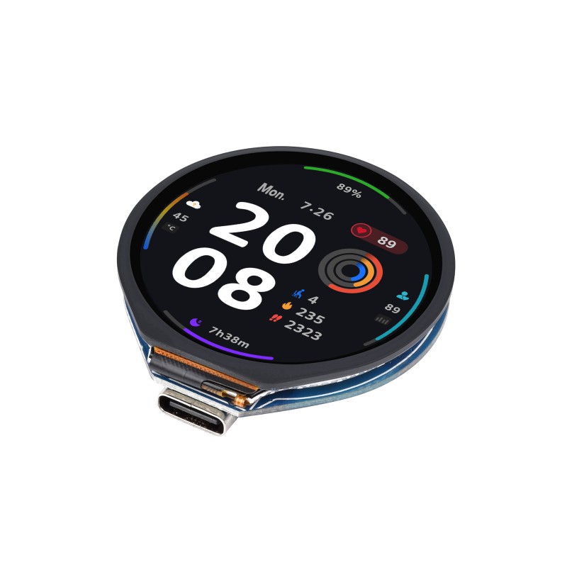
What it is: We have a full smartwatch tutorial that walks you through building a working watch face with the Waveshare ESP32-S3 1.28” round display. The missing piece in that guide is a proper case. This project gives you that case.
What You Need
- Waveshare ESP32-S3 Round Display 1.28” (~$20)
- 3.7V 250mAh LiPo battery
- 2x M2 screws (6mm)
- 22mm watch strap
Design Concept
This is a two-part snap-fit case: a front shell that frames the round display, and a back plate that clips onto it. No screws are visible from the outside.
Key dimensions to model in TinkerCAD:
- Display cutout: 32.5mm circle (the display itself is 32mm — leave 0.25mm clearance on each side)
- Battery compartment depth: 5mm (the 250mAh LiPo is 4.5mm thick)
- Strap slots: 22mm wide, 2mm tall, on the north and south of the case
- Snap-fit lip: 1mm overhang around the perimeter of the back plate
Search Printables.com for ESP32 round watch case 1.28 for an existing starting point. The Waveshare GC9A01 display form factor is common enough that several designs exist.
Print Settings
Print the front shell with the display face pointing down so the circular opening prints cleanly without supports. Print the back plate flat side down. Use 3 perimeter walls instead of the default 2 — this makes the snap-fit clips stronger.
Assembly Notes
Solder a JST 1.25mm connector to your LiPo if it does not have one. Tuck the battery under the board before snapping the case shut. The board mounts with double-sided foam tape against the back of the display.
Level Up
Add a small tactile button through the side wall, wired to a GPIO pin, to cycle through watch faces without opening the Arduino IDE.
Project 3: Desktop Weather Station Enclosure
What it is: An ESP32 connected to a BME280 sensor and a 0.96” OLED display makes a capable weather station. The code is in our weather dashboard tutorial. The problem is it looks like a pile of wires on your desk. This enclosure turns it into something you would actually leave out.
What You Need
- ESP32-S3 Dev Board
- 0.96” I2C OLED display (SSD1306)
- BME280 temperature/humidity/pressure sensor
- USB-C cable for power
Design Features
The enclosure has four key cutouts that you will add in TinkerCAD:
- Display window: 27mm × 15mm rectangular opening on the front face
- Sensor vent: A 10mm × 10mm grid of small holes (3mm each) on the left side wall — lets air reach the BME280 without letting dust in
- USB port slot: 10mm × 4mm opening on the back wall, aligned with your board’s USB-C port
- Desk stand: A 15-degree angled wedge fused to the bottom. This tilts the display toward you when sitting on a desk.
Search Printables.com for ESP32 OLED weather station enclosure or SSD1306 desktop case for base designs.
TinkerCAD Tip
Use the Hole shape type (red shapes) to cut the ventilation grid. Place a 3mm cylinder, mark it as a hole, duplicate it in a 3×3 grid using the Duplicate + Move method, then group everything to cut through the wall.
Print Settings
Print the enclosure with the front face pointing up. Add supports only if your printer cannot bridge the 27mm display opening (most modern printers can bridge 30mm with no supports). Print the stand separately and glue with super glue or use a snap joint.
Assembly Notes
Hot-glue the OLED display behind the window opening from the inside. Use double-sided foam tape for the BME280 — it must not be pressed against the ESP32 board or it will read higher temperatures from chip heat.
Level Up
Add a second OLED on the top face of the enclosure showing only the outdoor temperature, pulled from an Open-Meteo API call. Now it shows indoor vs. outdoor at a glance.
Project 4: Line-Following Robot Chassis
What it is: Instead of buying a pre-made robot chassis kit, you print your own. This gives you complete control over where motors, sensors, and batteries sit — and you can redesign individual parts as your robot improves without reprinting everything.
What You Need
- ESP32-S3 Dev Board
- 2x N20 gear motors with encoder (3V–6V, 100RPM)
- L298N or DRV8833 motor driver module
- 3x TCRT5000 IR line sensors
- 18650 battery holder (2-cell) + batteries
- M3 screws and heat-set inserts (optional but recommended)
Modular Chassis Design
The chassis is built from four printable modules that bolt together:
- Motor mounts: L-bracket style holders sized for N20 motors. Print 2.
- Main deck: A flat platform ~150mm × 100mm with bolt holes for the ESP32, motor driver, and battery holder at defined grid positions.
- Sensor bar: A front crossbar with three sensor slots spaced 15mm apart, pointing downward at a 10-degree angle.
- Battery bay: A removable tray on the underside that slides in and clicks into place.
Search Printables.com for N20 motor robot chassis modular or Makerworld for line follower 3d print.
Weight and Balance
Keep the battery as central and as low as possible — it is the heaviest part. If the robot tips forward, add a small drag wheel at the rear. Keep total weight under 250g for smooth sensor response on typical line-following tape.
Print Settings
Print motor mounts with 40% infill — they take the most mechanical stress. The main deck and battery tray can stay at 20%. Print motor mounts with the bolt holes vertical (not horizontal) for the strongest layer orientation.
Assembly Notes
Use M3 heat-set inserts in the motor mounts instead of screwing directly into PLA — PLA threads strip quickly under vibration. Press the inserts in with a soldering iron set to 200°C. Let each one cool for 60 seconds before moving.
Level Up
Add a second deck layer printed with standoffs to hold a Bluetooth module or an OLED status display, showing current speed, sensor readings, and lap time.
Project 5: Retro Game Console Shell
What it is: A handheld game console with an ESP32-S3, a 2.4” TFT display, six tactile buttons, and a small speaker. The shell is inspired by the classic GameBoy form factor — wide grip, landscape screen, two rows of buttons. It feels like a real handheld the moment you hold it.
What You Need
- ESP32-S3 Dev Board
- 2.4” ILI9341 TFT display (240×320px)
- 6x 6mm tactile push buttons
- 0.5W 8-ohm speaker
- 3.7V 1000mAh LiPo battery
- TP4056 charging module
Shell Design Features
The shell splits into two halves — front and back — joined by M3 screws through recessed holes (so no visible screw heads on the outside).
Key cutouts to add in TinkerCAD:
- Display window: 46mm × 35mm (matches the 2.4” ILI9341 active area)
- D-pad holes: 4× 7mm circles in a cross pattern, 13mm center-to-center
- Action buttons: 2× 7mm circles on the right side
- Start/Select: 2× 5mm circles centered below the display
- Speaker grille: A 20mm × 10mm rectangle filled with 1.5mm holes in a grid pattern
- USB-C charging slot: 10mm × 4mm on the bottom edge (for the TP4056 module)
- Ergonomic grips: Extend the left and right edges by 12mm and round them — your palms rest here
Search Makerworld for ESP32 gameboy handheld case or Printables for DIY handheld console 2.4 TFT. Many community designs exist with pre-sized cutouts for common displays.
TinkerCAD Tip
Use Workplane to build each internal mounting post separately. Each button needs a 6mm round post with a 0.5mm shorter height than the button stem — so the button sits flush with the shell surface.
Print Settings
Print both shell halves with the inside face pointing up (outside face down). This puts the best surface finish on the visible outside. Use 3 perimeter walls for strength around the button holes. Print a small test piece with just the button holes first — 6mm tactile switches have almost no tolerance and you may need to go to 6.2mm or 6.4mm for a smooth press.
Assembly Notes
Solder wires to the buttons and display before installing them — there is no room to solder inside the shell. Install the TP4056 module first (it sits at the bottom), then the battery, then the ESP32 board, then the display. Route all wires before closing the shell — there is no going back easily.
Level Up
Flash the ESP32 with an open-source game engine like Odroid-Go Arduino or write your own Snake or Pong clone in Arduino. The ILI9341 display is fast enough for smooth sprite animation.
Quick Reference: Where to Find STL Files
| Site | Best For | Free? |
|---|---|---|
| Printables.com | ESP32 and electronics enclosures | Yes |
| Thingiverse.com | Large older library, lots of remixes | Yes |
| Makerworld.com | Bambu Lab ecosystem, newer designs | Yes |
| Cults3d.com | Higher quality, some paid | Mixed |
Designing in TinkerCAD: The 10-Minute Setup
- Go to tinkercad.com — no download, runs in Chrome or Firefox
- Sign up with your email (free forever for personal use)
- Click Create new design
- Watch the built-in 5-minute tutorial — it covers everything you need
- Import any STL from the sites above as your starting point
- Change dimensions by clicking a shape and editing the numbers on the handles
The most important concept in TinkerCAD: red shapes are holes. Turn any shape red (using the object type menu on the right), overlap it with a solid, then click Group — and it cuts a hole. Every cutout in every project above works this way.
Next Steps
Once you have printed one of these, the next skill to learn is parametric CAD with Fusion 360 (free for students and hobbyists). It is more complex than TinkerCAD but lets you define dimensions that update automatically — so when you switch from one ESP32 board to another, you change one number and the whole case updates.
For the code side of these projects, see our other tutorials:
- Build Your Own Smartwatch — pairs with Project 2
- ESP32 Practical Home Projects — pairs with Project 3
- ESP32 Robotics & Lego Projects — pairs with Project 4