Parent info
Parts you need
Affiliate links — we may earn a small commission
Try this circuit in your browser!
Run the code, press the buttons and watch what happens — before you buy any parts. No account needed.
Open in Simulator →Every FPS game shows your ammo. Now your NERF blaster does too.
Imagine this: you’re in the middle of a NERF battle. You glance down at the OLED display mounted on your blaster’s rail — 8 ROUNDS. You fire twice. It says 6. You empty the clip — it flashes !! RELOAD !! in big letters. You slap in a fresh clip, hit the reset button — back to 12.
No guessing. No counting in your head. Real game mechanics on real hardware.
Builds in 2 hours. For about $24.
What you’ll need
| Part | What it does | Price |
|---|---|---|
| ESP32-S3-DevKitC-1 | The brain. Counts darts via hardware interrupt — never misses a shot. | ~$12 |
| SSD1306 OLED display 0.96” | Shows ammo count in huge text. I2C connection — only 2 data wires. | ~$3 |
| IR break-beam sensor pair | Emitter + receiver. Dart flies through, breaks the beam, count decrements. | ~$4 |
| Small LiPo battery (3.7V 500mAh) | Compact power for wearing on the blaster. Or use USB power bank. | ~$5 |
Total: ~$24 | Time: ~2 hours | Difficulty: ●●○○○
How it works (60 seconds)
Think of it like this: the IR beam is a tripwire stretched across the dart barrel.
The emitter (an infrared LED) shines a constant invisible beam across the barrel opening to the receiver on the other side. When nothing is there, the beam is intact — the receiver sees light and outputs HIGH. When a dart flies through, it blocks the beam for a few milliseconds — the receiver output drops to LOW.
That momentary LOW triggers a hardware interrupt on the ESP32. An interrupt is like tapping the CPU on the shoulder in the middle of anything else it’s doing. The CPU immediately runs a tiny function (dartFired()), decrements the ammo count, and returns to whatever it was doing.
This happens in under a microsecond. A dart traveling at 20 m/s is about 6 cm across the barrel — it takes ~3ms to pass. The interrupt fires instantly at the leading edge, counts it, and is done before the dart has even finished crossing.
The OLED shows the current count in big text. When ammo hits zero, the screen switches to !! RELOAD !!. The BOOT button on the ESP32 resets the count for a reload.
Step 0: Mount the beam sensor on your blaster
Time: ~10 minutes
The IR emitter and receiver need to face each other across the dart path — not along it.
Best mounting location: Just inside the barrel exit, or on a bracket that spans the muzzle from side to side. The dart passes between the emitter and receiver.
- 3D print or improvise a bracket that holds the emitter on one side of the barrel and the receiver directly opposite.
- Make sure the beam path is perpendicular to the dart path — the dart should cross the beam cleanly.
- Search Printables for “nerf oled ammo counter” — many designs include the beam bracket and rail mount in one part.
Check: Wave your finger through the gap between the emitter and receiver. You should see the small LED on the receiver module flicker or change when your finger breaks the beam. If it doesn’t respond, the emitter isn’t powered or the alignment is off.
Step 1: Wire it up
Time: ~10 minutes
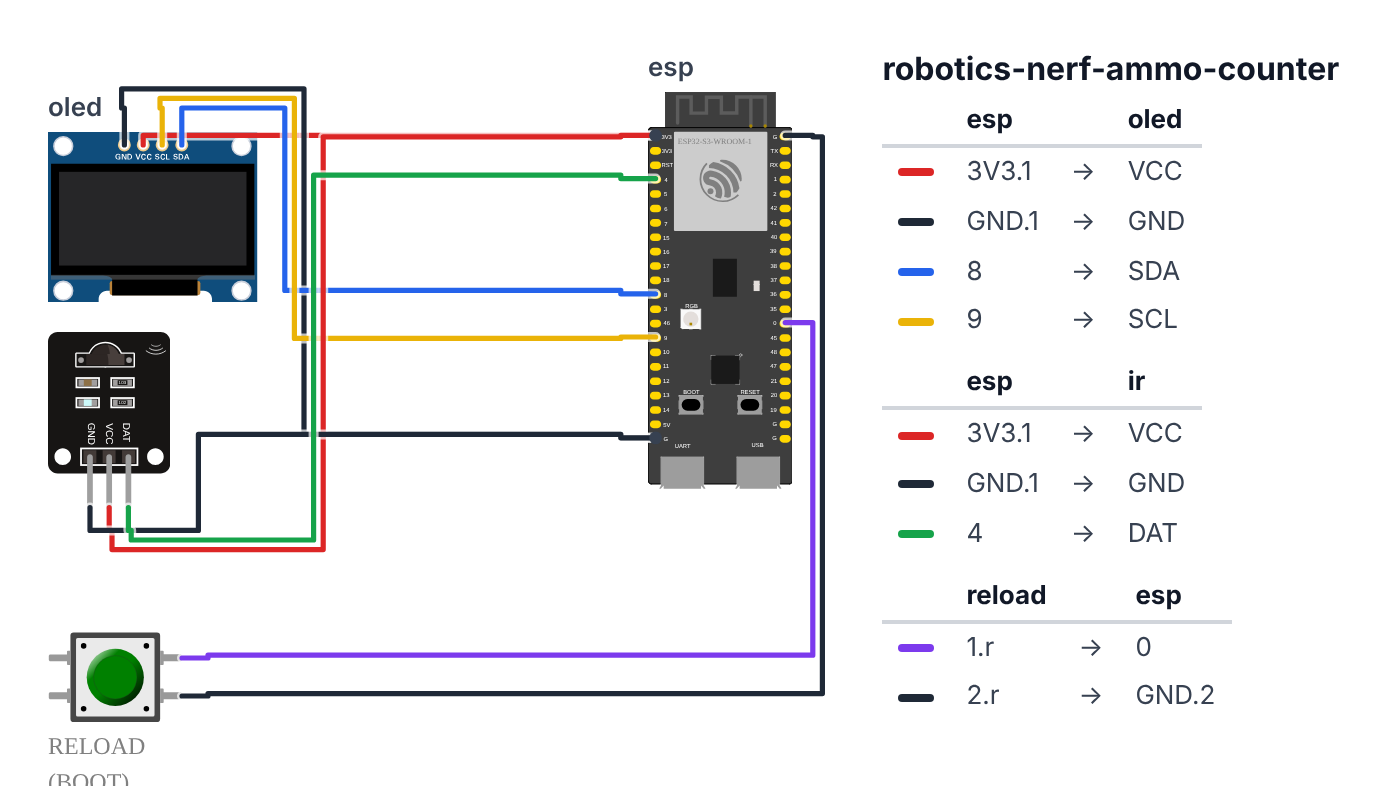
OLED Display (I2C — only 4 wires):
- OLED VCC → ESP32 3.3V — red wire
- OLED GND → ESP32 GND — black wire
- OLED SDA → ESP32 GPIO 8 (C6: GPIO 6) — blue wire
- OLED SCL → ESP32 GPIO 9 (C6: GPIO 7) — yellow wire
IR Break-Beam Sensors: 5. Emitter VCC → ESP32 3.3V — red wire 6. Emitter GND → ESP32 GND — black wire 7. Receiver VCC → ESP32 3.3V — red wire 8. Receiver GND → ESP32 GND — black wire 9. Receiver OUT → ESP32 GPIO 4 (C6: GPIO 23) — green wire
Reload button:
- Uses the built-in BOOT button on GPIO 0 (C6: GPIO 9) — no extra hardware needed
Check: Six wires total (not counting the button, which uses existing hardware). The OLED and emitter both run on 3.3V. The receiver output goes to GPIO 4 (C6: GPIO 23). Triple-check SDA/SCL are on 8/9 (C6: 6/7) — swapping them is a common mistake.
Step 2: Flash the code
Time: ~5 minutes
Install Adafruit SSD1306 and Adafruit GFX libraries in Arduino IDE (Tools → Manage Libraries). Select ESP32S3 Dev Module. Upload:
The big picture first. This program has two separate “brains” running at the same time:
- A hardware interrupt that fires the instant a dart breaks the IR beam — faster than any loop can check.
- A main loop that draws the HUD on the screen 20 times per second and watches the reload button.
Interrupts are like a doorbell. Your main loop is watching TV. When the doorbell rings (dart breaks beam), the TV-watching stops instantly, you run to the door (count down ammo), then come back to TV. This is why no dart ever gets missed even at high speed.
// ========== CHOOSE YOUR BOARD ==========
// Uncomment the line for YOUR board:
#define BOARD_S3    // ESP32-S3-DevKitC-1
//#define BOARD_C6  // ESP32-C6-DevKitC-1
// ========================================

#ifdef BOARD_S3
  #define PIN_IR_BEAM          4
  #define PIN_RELOAD_BTN       0
  #define PIN_SDA              8
  #define PIN_SCL              9
#endif
#ifdef BOARD_C6
  #define PIN_IR_BEAM          23
  #define PIN_RELOAD_BTN       9
  #define PIN_SDA              6
  #define PIN_SCL              7
#endif

#include <Wire.h>
#include <Adafruit_GFX.h>
#include <Adafruit_SSD1306.h>

#define SCREEN_W  128
#define SCREEN_H   64
#define OLED_ADDR 0x3C
Adafruit_SSD1306 display(SCREEN_W, SCREEN_H, &Wire, -1);

#define MAX_AMMO     12
volatile int ammoLeft   = MAX_AMMO;
volatile int totalShots = 0;
unsigned long lastShot  = 0;
#define DEBOUNCE_MS 150

void IRAM_ATTR dartFired() {
  if (millis() - lastShot < DEBOUNCE_MS) return;
  if (ammoLeft > 0) {
    ammoLeft--;
    totalShots++;
  }
  lastShot = millis();
}

void drawHUD() {
  display.clearDisplay();

  if (ammoLeft == 0) {
    display.setTextSize(2);
    display.setTextColor(SSD1306_WHITE);
    display.setCursor(8, 10);
    display.println("!! RELOAD !!");
    display.setTextSize(1);
    display.setCursor(20, 50);
    display.println("Press BOOT to reset");
  } else {
    display.setTextSize(4);
    display.setTextColor(SSD1306_WHITE);
    display.setCursor(ammoLeft < 10 ? 48 : 28, 8);
    display.println(ammoLeft);

    display.setTextSize(1);
    display.setCursor(0, 0);
    display.println("AMMO");

    display.drawLine(0, 52, 128, 52, SSD1306_WHITE);

    display.setCursor(0, 55);
    display.print("SHOTS: ");
    display.print(totalShots);
    display.print("  MAX: ");
    display.print(MAX_AMMO);

    if (ammoLeft <= 3) {
      display.setTextSize(1);
      display.setCursor(70, 0);
      display.println("LOW!");
    }
  }
  display.display();
}

void setup() {
  Serial.begin(115200);

  Wire.begin(PIN_SDA, PIN_SCL);
  if (!display.begin(SSD1306_SWITCHCAPVCC, OLED_ADDR)) {
    Serial.println("OLED not found! Check wiring.");
    while(1);
  }
  display.clearDisplay();
  display.setTextColor(SSD1306_WHITE);

  display.setTextSize(2);
  display.setCursor(4, 10);
  display.println("BUILDCOOL");
  display.setTextSize(1);
  display.setCursor(10, 40);
  display.println("NERF BATTLE HUD v1.0");
  display.display();
  delay(2000);

  pinMode(PIN_IR_BEAM, INPUT_PULLUP);
  attachInterrupt(digitalPinToInterrupt(PIN_IR_BEAM), dartFired, FALLING);

  pinMode(PIN_RELOAD_BTN, INPUT_PULLUP);

  ammoLeft = MAX_AMMO;
  drawHUD();
  Serial.println("HUD ready. Shoot something.");
}

void loop() {
  if (digitalRead(PIN_RELOAD_BTN) == LOW) {
    delay(50);
    if (digitalRead(PIN_RELOAD_BTN) == LOW) {
      ammoLeft = MAX_AMMO;
      Serial.println("RELOADED");
      while(digitalRead(PIN_RELOAD_BTN) == LOW) delay(10);
    }
  }

  drawHUD();
  delay(50);
}
Line-by-line: what every line does and why
Lines 1–3: Borrowing the instruction books
#include <Wire.h>
#include <Adafruit_GFX.h>
#include <Adafruit_SSD1306.h>
#include means “grab this instruction book.” Wire.h handles the two-wire I2C communication to the display. Adafruit_GFX provides the drawing tools (text, lines, shapes). Adafruit_SSD1306 is the specific driver for this OLED model.
Lines 5–8: Setting up the display
#define SCREEN_W  128
#define SCREEN_H   64
#define OLED_ADDR 0x3C
Adafruit_SSD1306 display(SCREEN_W, SCREEN_H, &Wire, -1);
The OLED is 128 dots wide and 64 dots tall — those dots are called pixels. 0x3C is the display’s I2C address — like a house number on a two-wire street. Multiple devices can share the same two wires as long as each has a unique address. The -1 means “no reset pin.” display is the name we give this screen — from now on, when we write display.something, we’re talking to it.
Lines 7–18: Naming the pins
#define PIN_IR_BEAM          4
#define PIN_RELOAD_BTN       0
Pin 4 (C6: pin 23) receives the signal from the IR receiver. When a dart breaks the beam, this pin goes from HIGH to LOW. Pin 0 (C6: pin 9) is the built-in BOOT button on the ESP32 board — we use it as the reload button for free.
Lines 13–17: The ammo counter variables
#define MAX_AMMO     12
volatile int ammoLeft   = MAX_AMMO;
volatile int totalShots = 0;
unsigned long lastShot  = 0;
#define DEBOUNCE_MS 150
MAX_AMMO is how many darts your clip holds — change it to 6, 18, or 25 to match your blaster. The word volatile is critical: it tells the computer “this number can change at any moment because an interrupt might update it — always read fresh from memory, never use a cached copy.” Without volatile, the main loop might read a stale value and show the wrong ammo count. lastShot records when the last dart fired (in milliseconds), and DEBOUNCE_MS = 150 means “ignore anything within 150ms of the last shot” — one dart passing through can cause multiple signals due to vibration.
dartFired(): The interrupt function
void IRAM_ATTR dartFired() {
  if (millis() - lastShot < DEBOUNCE_MS) return;
  if (ammoLeft > 0) {
    ammoLeft--;
    totalShots++;
  }
  lastShot = millis();
}
IRAM_ATTR forces this function to live in the chip’s internal RAM, not in flash memory. Interrupts must live in RAM because flash can occasionally be unavailable — if the function lived in flash and fired at the wrong moment, the chip would crash. It’s like the difference between a fire alarm (must always work, lives in battery-powered RAM) versus a regular reminder (can live in a file on disk).
millis() is a stopwatch that counts milliseconds since power-on. If fewer than 150ms have passed since the last shot, return exits immediately — ignoring vibration echoes. ammoLeft-- subtracts 1 from ammo. -- means “reduce by 1.”
drawHUD(): Painting the screen
display.clearDisplay();
...
display.display();
The screen works like a whiteboard with a projector. clearDisplay() wipes the invisible whiteboard. All the display.print() and display.drawLine() calls draw on the invisible whiteboard. Then display.display() projects it onto the real screen all at once. This prevents flickering — without it, you’d see letters appearing one at a time.
The HUD shows the big ammo count in size-4 text (enormous), with “AMMO” label in size-1 text above it. When ammo hits 0, the entire screen switches to the !! RELOAD !! message.
setup(): One-time startup
Wire.begin(PIN_SDA, PIN_SCL);
attachInterrupt(digitalPinToInterrupt(PIN_IR_BEAM), dartFired, FALLING);
Wire.begin(PIN_SDA, PIN_SCL) tells the I2C bus which physical pins to use: pin 8 (C6: pin 6) carries data, pin 9 (C6: pin 7) carries the clock beat. attachInterrupt is the key line: “when pin 4 (C6: pin 23) falls from HIGH to LOW (FALLING), immediately run dartFired().” digitalPinToInterrupt converts the pin number to the hardware interrupt number — different ESP32 boards sometimes number them differently.
INPUT_PULLUP on the IR beam pin means “normally HIGH — only goes LOW when triggered.” This prevents false alarms when nothing is connected.
loop(): The ongoing HUD refresh
if (digitalRead(PIN_RELOAD_BTN) == LOW) {
  delay(50);
  if (digitalRead(PIN_RELOAD_BTN) == LOW) {
    ammoLeft = MAX_AMMO;
  }
}
drawHUD();
delay(50);
The button reads LOW when pressed (because INPUT_PULLUP keeps it HIGH normally). The double-check after delay(50) is debounce — a bouncy button can flicker HIGH-LOW-HIGH in milliseconds, so we wait 50ms and check again. If still LOW, it’s a real press. ammoLeft = MAX_AMMO resets to full. Then drawHUD() updates the screen. delay(50) = 20 updates per second — plenty smooth.
The whole thing in one sentence
When a dart breaks the IR beam, a hardware interrupt fires instantly, counts down ammo, and marks the time. The main loop draws the current count on screen 20 times per second. Press BOOT to reload.
First thing to try: Wave your hand through the IR beam gap. The number on the OLED should drop by 1 each time you break the beam. Wave fast repeatedly — notice the debounce prevents double-counts.
Check: Upload succeeds. The OLED should show “BUILDCOOL — NERF BATTLE HUD v1.0” for 2 seconds, then switch to the ammo HUD showing 12 in large text.
Step 3: Test the counter
Time: ~2 minutes
- Wave your hand through the IR beam gap (between emitter and receiver).
- The number on the OLED should decrement by 1 each time you break the beam.
- When it reaches 0, the screen should switch to
!! RELOAD !!. - Press the BOOT button — count resets to 12 and the normal HUD returns.
Calibration: If one dart triggers the count multiple times (dart is long or wobbles), increase DEBOUNCE_MS from 150 to 250.
Step 4: Mount it on your blaster
Put the board and display in a 3D-printed rail enclosure and clip it to the tactical rail on your blaster. Run the LiPo battery inside or behind the enclosure.
Set MAX_AMMO in the code to match your clip:
#define MAX_AMMO 6— for revolver-style blasters#define MAX_AMMO 12— standard straight clip#define MAX_AMMO 18— banana clip / extended#define MAX_AMMO 25— drum magazine
Re-upload after changing. Now the HUD matches your actual gear.
What just happened (what you learned)
-
Hardware interrupts — Without interrupts, you’d check
digitalRead(PIN_IR_BEAM)in every loop. At 50ms per loop, a dart traveling 20 m/s crosses the barrel in 3ms — you’d miss most shots. Hardware interrupts solve this: when the pin changes, the CPU immediately stops whatever it’s doing and runsdartFired(). The interrupt fires within microseconds of the beam breaking. -
IRAM_ATTR — The ESP32’s flash memory can be temporarily unavailable during certain operations. If an ISR lives in flash and fires at that moment, the CPU crashes.
IRAM_ATTRcopies the function to internal RAM, which is always available. Every function called from an ISR must also be in IRAM. This is ESP32-specific. -
volatile keyword — Variables shared between an ISR and main code must be
volatile. Without it, the compiler might cacheammoLeftin a CPU register and never re-read it from RAM. Main code would always see the old value.volatiletells the compiler: “this can change at any time outside normal program flow — always read fresh from memory.” -
SSD1306 and I2C — The OLED communicates over I2C — two wires (SDA and SCL). Many devices can share the same I2C bus by having different addresses (0x3C is common for SSD1306).
display.display()pushes the complete 128×64 pixel framebuffer to the OLED in one I2C transaction. Build the frame in memory first, then send all at once — prevents flickering.
Level Up
Add a game timer. Hold BOOT for 2 seconds to start a 3-minute countdown. Store gameStart = millis(). In drawHUD(), calculate remaining = 180000 - (millis() - gameStart) and display as MM:SS in the top-right corner. When it hits zero, flash “TIME!”.
Magazine select mode. Hold BOOT for 2 seconds to cycle through clip sizes: 6, 12, 18, 25. Show the selected size briefly on the OLED. Set ammoLeft = selectedMag on next short press. Different NERF blasters hold different amounts — the HUD should match your gear.
Audio feedback with a piezo buzzer. Wire a passive piezo to GPIO 46 (C6: GPIO 10). When a dart fires: tone(46, 1000, 30) — short blip (on the C6 write 10 instead of 46). When ammo hits 3: lower-pitched warning tone. When ammo hits 0: a short reload melody. Audio feedback in the heat of a battle is more useful than expected.
★★ You completed: NERF Ammo Counter HUD!
Troubleshooting
| Problem | Fix |
|---|---|
| OLED shows nothing | Check SDA on GPIO 8 and SCL on GPIO 9 (C6: GPIO 6 and 7). Run a basic I2C scanner sketch to confirm the display responds at address 0x3C. |
| OLED shows “OLED not found!” | Wrong I2C address — try 0x3D in display.begin(SSD1306_SWITCHCAPVCC, 0x3D). Or check 3.3V is connected. |
| Count doesn’t decrement when I wave my hand | IR receiver output not reaching GPIO 4 (C6: GPIO 23). Check receiver is powered (3.3V). Check OUT wire to GPIO 4 (C6: GPIO 23). Use Serial Monitor — the ISR doesn’t print but you can add Serial.println("DART") inside dartFired() temporarily. |
| Count decrements multiple times per dart | Increase DEBOUNCE_MS to 250 or 300. |
| Count decrements without anything firing | Sunlight or bright room light is hitting the IR receiver. Shield it from ambient IR, or move the sensor. |
| BOOT button doesn’t reload | Press firmly — BOOT needs full contact. Some boards require a proper tactile press, not just a touch. |
| Upload fails | Hold BOOT while you press RESET to enter flash mode, then release BOOT and upload again. |