Parent info
Parts you need
Affiliate links — we may earn a small commission
Try this circuit in your browser!
Run the code, press the buttons and watch what happens — before you buy any parts. No account needed.
Open in Simulator →The laser alarm from every heist movie. Real. Working. $20.
Imagine this: a red laser beam crosses your doorway, invisible unless you know to look for it. Someone walks through. Alarm fires. Your phone buzzes. You have five seconds to decide your response.
This is that build. Laser module on one side of the door, photoresistor on the other, ESP32 in the middle. When the beam breaks, the alarm sounds.
In 45 minutes. For about $20.
What you’ll need
| Part | What it does | Price |
|---|---|---|
| ESP32-S3-DevKitC-1 | Reads the light sensor, runs the alarm, sends Telegram alerts | ~$12 |
| 5mW Laser module (650nm) | Projects the beam — any KY-008 compatible laser works | ~$3 |
| LDR Photoresistor | Detects the beam — alarm triggers when light drops suddenly | ~$1 |
| 10kΩ Resistors ×2 | Builds the voltage divider circuit that the LDR needs | ~$2 |
| Passive Buzzer | Sounds the alarm — must be passive (not active) for tone() to work | ~$2 |
| Breadboard + jumper wires | Connects everything, no soldering needed | ~$3 |
Total: ~$20 | Time: ~45 minutes | Difficulty: ●●○○○
Note: The laser module must be on one side of the doorway and the LDR on the other. You’ll need a way to run a thin wire across — tape along the top of the door frame works fine.
How it works (60 seconds)
Think of it like a light switch that breaks when someone walks through.
The laser fires a beam straight at the LDR. When the beam is hitting the LDR, its resistance is low — the analog reading is high (around 3200 out of 4095). When a foot, hand, or sibling breaks the beam, the resistance shoots up — the reading drops sharply. The ESP32 reads this 20 times per second and triggers the alarm the moment it detects that drop.
The “voltage divider” circuit is what makes this work: two resistors plus the LDR create a voltage between 0V and 3.3V that the ESP32 can actually measure.
Step 0: Plan your doorway layout
Time: ~5 minutes
Before wiring — figure out your placement.
The laser goes on one side of the doorway. The LDR (and your ESP32) go on the other. You need to run one wire from the laser to the ESP32 across the doorway — tape it along the top of the door frame, or run it under a rug if crossing the floor.
Height: Aim for about 70-80cm off the ground — above where a pet might walk, below where a person can step over it unnoticed.
Alignment is everything. The laser beam needs to hit the LDR directly. Mount the LDR on a small lump of Blu-tack so you can angle it precisely.
Check: Before wiring anything to the ESP32, hold the laser against the LDR and look at the LDR — you should see a bright red dot on it. That’s the alignment you’re aiming for with it mounted.
Step 1: Wire it up
Time: ~10 minutes
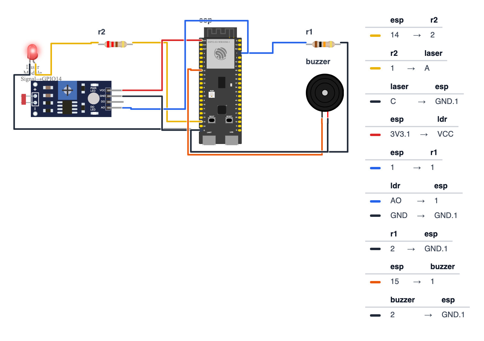
You have three separate things to connect: the laser, the LDR voltage divider, and the buzzer.
Laser Module (3 wires):
- Laser VCC → ESP32 3.3V — red wire
- Laser GND → ESP32 GND — black wire
- Laser Signal (S pin) → ESP32 GPIO 14 (C6: GPIO 4) — yellow wire
(The wiring picture draws the laser as a red LED with a 220Ω resistor. Your laser module already has its resistor built in, so you don’t need an extra one.)
LDR Voltage Divider (on the opposite side of the doorway):
3.3V ──── [LDR] ──── GPIO 1 ──── [10kΩ resistor] ──── GNDIn plain English: 4. 3.3V → one leg of the LDR 5. Other leg of the LDR → breadboard row (junction point) 6. Junction point → ESP32 GPIO 1 (ADC pin) — blue wire 7. Junction point → one leg of the 10kΩ resistor 8. Other leg of the resistor → GND
The LDR sits on the 3.3V side, so more laser light means a higher reading — exactly what the code expects.
Buzzer (2 wires): 9. Buzzer + → ESP32 GPIO 15 (C6: GPIO 3) — orange wire 10. Buzzer - → ESP32 GND — black wire
Check: Count your connections: 3 for laser + 5 for LDR circuit + 2 for buzzer = 10 wires total. GPIO 1 must be on the ADC side — not all GPIO pins on an ESP32 can do analog reads.
Step 2: Flash the code
Time: ~5 minutes
Install the UniversalTelegramBot library in Arduino IDE (Sketch → Manage Libraries), then upload this code:
The big picture first. This program turns your doorway into a silent laser alarm:
- The laser fires a continuous beam across the doorway at the LDR (light sensor) on the other side.
- The LDR is like an eye — when the laser beam hits it, it sees bright light. When someone walks through the beam, the light suddenly disappears.
- The ESP32 reads the LDR 20 times per second. If the reading drops sharply below normal (the beam was broken), it fires the buzzer and texts your phone.
- Before arming, the code calibrates — it measures what “normal” looks like so it knows what “broken” means.
// ========== CHOOSE YOUR BOARD ==========
// Uncomment the line for YOUR board:
#define BOARD_S3    // ESP32-S3-DevKitC-1
//#define BOARD_C6  // ESP32-C6-DevKitC-1
// ========================================

#ifdef BOARD_S3
  #define PIN_LASER   14
  #define PIN_LDR      1
  #define PIN_BUZZER  15
#endif
#ifdef BOARD_C6
  #define PIN_LASER    4
  #define PIN_LDR      1
  #define PIN_BUZZER   3
#endif

#include <WiFi.h>
#include <WiFiClientSecure.h>
#include <UniversalTelegramBot.h>

const char* WIFI_SSID     = "YourWiFiName";
const char* WIFI_PASSWORD = "YourWiFiPassword";
const char* BOT_TOKEN     = "YOUR_TELEGRAM_BOT_TOKEN";
const char* CHAT_ID       = "YOUR_TELEGRAM_CHAT_ID";

int baselineReading   = 0;
const int DROP_THRESHOLD = 500;
const unsigned long LOCKOUT_MS = 8000;
unsigned long lastAlertTime = 0;

WiFiClientSecure client;
UniversalTelegramBot bot(BOT_TOKEN, client);

void calibrate() {
  Serial.println("Calibrating laser baseline...");
  long sum = 0;
  for (int i = 0; i < 50; i++) {
    sum += analogRead(PIN_LDR);
    delay(20);
  }
  baselineReading = sum / 50;
  Serial.println("Baseline LDR reading: " + String(baselineReading));
  Serial.println("Trigger threshold: " + String(baselineReading - DROP_THRESHOLD));
}

void setup() {
  Serial.begin(115200);
  pinMode(PIN_LASER, OUTPUT);
  pinMode(PIN_BUZZER, OUTPUT);
  digitalWrite(PIN_LASER, HIGH);
  digitalWrite(PIN_BUZZER, LOW);

  WiFi.begin(WIFI_SSID, WIFI_PASSWORD);
  Serial.print("Connecting to WiFi");
  while (WiFi.status() != WL_CONNECTED) {
    delay(500); Serial.print(".");
  }
  Serial.println("\nConnected.");
  client.setInsecure();

  delay(2000);
  calibrate();

  Serial.println("Operation Red Line: ARMED");
}

void loop() {
  int ldrValue = analogRead(PIN_LDR);

  if (ldrValue < (baselineReading - DROP_THRESHOLD)) {
    unsigned long now = millis();
    if (now - lastAlertTime > LOCKOUT_MS) {
      lastAlertTime = now;

      Serial.println("BEAM BROKEN! LDR: " + String(ldrValue));

      for (int i = 0; i < 3; i++) {
        tone(PIN_BUZZER, 1200, 300);
        delay(400);
        tone(PIN_BUZZER, 800, 300);
        delay(400);
      }
      noTone(PIN_BUZZER);

      String msg = "LASER TRIPWIRE TRIGGERED!\n";
      msg += "LDR reading: " + String(ldrValue) + "\n";
      msg += "(baseline was " + String(baselineReading) + ")";
      bot.sendMessage(CHAT_ID, msg, "");
    }
  }

  delay(50);
}
Line-by-line: what every line does and why
Lines 1–3: Borrowing ready-made tools
#include <WiFi.h>
#include <WiFiClientSecure.h>
#include <UniversalTelegramBot.h>
#include grabs instruction books. WiFi connects to your network. WiFiClientSecure handles encrypted (HTTPS) connections — Telegram requires encryption so nobody can read your alerts on the way to your phone. UniversalTelegramBot gives you bot.sendMessage() to text your phone.
Lines 7–25: Settings
const char* WIFI_SSID     = "YourWiFiName";
...
#define PIN_LASER   14
#define PIN_LDR      1
#define PIN_BUZZER  15
const means “locked — never changes.” char* stores a word (string). int stores a whole number. #define gives a pin number a name.
PIN_LASER 14 — the laser’s signal wire connects to GPIO 14 (C6: GPIO 4). Writing HIGH to this pin turns the laser on.
PIN_LDR 1 — the light sensor connects to GPIO 1. This is an ADC pin (Analog to Digital Converter) — it can measure voltage levels from 0 to 3.3V and converts them to numbers from 0 to 4095. Not all GPIO pins on the ESP32 can do this; GPIO 1 is one that can.
PIN_BUZZER 15 — the buzzer’s positive leg connects here (C6: GPIO 3).
Lines 13–17: Alarm logic variables
int baselineReading   = 0;
const int DROP_THRESHOLD = 500;
const unsigned long LOCKOUT_MS = 8000;
unsigned long lastAlertTime = 0;
baselineReading — this is where the code stores “what the LDR reads when the beam is hitting it normally.” Think of it as writing down the normal temperature so you can tell when it’s fever-level high. Starts at 0 and gets set during calibration.
DROP_THRESHOLD = 500 — how far below baseline the reading must drop before we call it an alarm. If baseline is 3200 and threshold is 500, anything below 2700 triggers the alarm. Increase this number if you get false alarms; decrease it if the alarm misses crossings.
LOCKOUT_MS = 8000 — 8,000 milliseconds = 8 seconds. After an alarm, the system ignores new triggers for 8 seconds. Without this, one person walking through slowly could fire 160 alarms (20 checks per second × 8 seconds).
lastAlertTime = 0 — a sticky note that records when the last alert fired. Used with millis() to enforce the 8-second lockout.
Lines 23–33: calibrate() — measuring “normal”
void calibrate() {
  long sum = 0;
  for (int i = 0; i < 50; i++) {
    sum += analogRead(PIN_LDR);
    delay(20);
  }
  baselineReading = sum / 50;
  ...
}
void calibrate() is a function — a recipe with a name. When called, it takes 50 LDR readings and averages them.
long sum = 0 — a big number box to accumulate the total. long is a larger version of int — needed because 50 readings of ~3200 each adds up to 160,000, which is too big for a regular int.
for (int i = 0; i < 50; i++) — a loop that runs 50 times. i starts at 0, increments by 1 (i++), and stops when it reaches 50.
sum += analogRead(PIN_LDR) — += means “add to the current sum.” analogRead() returns a number from 0 (no light) to 4095 (maximum light).
delay(20) — wait 20ms between readings. With 50 readings × 20ms each = 1 second of sampling.
baselineReading = sum / 50 — divide the total by 50 to get the average. Why average 50 readings instead of just one? Electricity is noisy — any single reading might be slightly off. Averaging 50 readings is like asking 50 people “how warm is this room?” and trusting the average over any single answer.
Lines 35–55: setup() — the morning routine
digitalWrite(PIN_LASER, HIGH);
digitalWrite(PIN_BUZZER, LOW);
digitalWrite(pin, value) — set a pin to HIGH (3.3V, full power on) or LOW (0V, off).
- Laser HIGH = laser beam is ON. Must be on before calibration so the LDR sees the beam.
- Buzzer LOW = silent at startup.
After connecting WiFi and client.setInsecure() (skip SSL certificate checking, fine for a bedroom alarm):
delay(2000) — wait 2 seconds for the laser to reach full brightness before measuring the baseline.
calibrate() — take the 50-reading average. Now the code knows what “beam hitting LDR cleanly” looks like.
Lines 57–84: loop() — watches continuously
void loop() {
  int ldrValue = analogRead(PIN_LDR);

  if (ldrValue < (baselineReading - DROP_THRESHOLD)) {
    unsigned long now = millis();
    if (now - lastAlertTime > LOCKOUT_MS) {
      lastAlertTime = now;
      ...
      for (int i = 0; i < 3; i++) {
        tone(PIN_BUZZER, 1200, 300);
        delay(400);
        tone(PIN_BUZZER, 800, 300);
        delay(400);
      }
      noTone(PIN_BUZZER);
      bot.sendMessage(CHAT_ID, msg, "");
    }
  }
  delay(50);
}
loop() beats like a heartbeat — runs thousands of times per second.
int ldrValue = analogRead(PIN_LDR) — read the current light level. 4095 = laser beam bright on the LDR. Near 0 = darkness (beam broken).
if (ldrValue < (baselineReading - DROP_THRESHOLD)) — “is the current reading more than 500 below the calibrated normal?” If the baseline was 3200, this fires when the reading drops below 2700.
unsigned long now = millis() — read the stopwatch. millis() returns how many milliseconds have passed since power-on.
now - lastAlertTime > LOCKOUT_MS — “has more than 8 seconds passed since the last alert?” Both checks together mean: “beam is broken AND we’re not in the cooldown window.”
for (int i = 0; i < 3; i++) — the buzzer loop runs 3 times.
tone(PIN_BUZZER, 1200, 300) — play 1200 Hz for 300 milliseconds. Hz (Hertz) is “vibrations per second.” 1200 Hz is a high-pitched beep. 800 Hz is lower. Alternating creates the alarm-style sound.
noTone(PIN_BUZZER) — silence the buzzer. Without this, some buzzers would keep beeping after the tone() duration ends.
delay(50) — check 20 times per second. Fast enough to catch any crossing.
The whole thing in one sentence
On startup, the code turns on the laser and measures the LDR baseline; then in loop() it watches 20 times per second for the LDR to drop sharply below that baseline, and when the beam breaks it fires the buzzer and texts your phone — then waits 8 seconds before watching again.
First thing to try: cover the LDR with your finger (simulating a broken beam). Watch Serial Monitor — you should see “BEAM BROKEN!” and the buzzer should fire. If not, the baseline was measured incorrectly — press Reset on the ESP32 to recalibrate with the laser properly aimed.
Check: Open Serial Monitor at 115200 baud. You should see the calibration running: “Baseline LDR reading: XXXX”. If the baseline is below 2000, your laser isn’t hitting the LDR — adjust alignment now before continuing.
Step 3: Align the laser
Time: ~5 minutes
This is the most important step. Everything else is easy. Alignment is what makes this work reliably.
- Power the ESP32 and laser on.
- Look at the Serial Monitor — you’ll see calibration running automatically.
- If baseline is above 3000 — perfect alignment. You’re done.
- If it’s between 2000-3000 — acceptable. The alarm will still work.
- If it’s below 2000 — the laser is missing the LDR. Adjust the laser angle and run
calibrate()again (press Reset on the ESP32 to re-run setup).
Quick re-calibration: Press the Reset button on your ESP32 any time to re-run the calibration function with the current alignment.
Check: Wave your hand through the beam. The buzzer should fire with three alternating tones. Your phone should buzz with the Telegram message within 3 seconds.
Step 4: Arm it!
Time: ~2 minutes
The alarm is running. Test a few things:
- Walk through at normal speed — should trigger
- Walk through very slowly — should still trigger (the beam is just broken, not the speed)
- Wave your hand quickly — may or may not trigger depending on speed (this is a feature — fast objects might not register)
- Try to step over it — notice how low it is
Sensitivity tuning: If you get false alarms from room lighting changes, increase DROP_THRESHOLD from 500 to 800. If the alarm misses slow crossings, decrease it to 300.
What just happened (what you learned)
You built an analog sensor circuit — different from the digital PIR in the Room Alarm project.
-
Voltage divider uses two resistors (or a resistor and an LDR) to create a voltage between 0V and 3.3V. When the LDR is lit by the laser, its resistance drops and voltage at the midpoint rises. When the beam breaks, resistance increases and voltage drops.
analogRead()measures that voltage. -
ADC (Analog to Digital Converter) converts a real-world voltage (0–3.3V) to a number (0–4095). Only certain GPIO pins on the ESP32 have ADC hardware — that’s why the LDR must go on GPIO 1, not just any pin.
-
Calibration measures “normal” as a baseline so the code knows what “broken” looks like. Without calibration, a lamp turning on could trigger the alarm. Calibration anchors the threshold to the actual environment.
-
Averaging multiple readings before storing a baseline removes electrical noise — like asking 50 people what temperature the room is and averaging their answers instead of trusting just one thermometer reading.
Level Up
Remote recalibration: Send /calibrate to your Telegram bot and have the ESP32 re-run the calibration without you needing to press the Reset button. Use bot.getUpdates() to check for incoming Telegram commands.
Beam break duration filter: The alarm fires the moment the beam breaks. Add a timer: only trigger if the beam stays broken for more than 500ms. A quick wave won’t trigger it, but a person walking through at normal speed will.
Pulse mode power saving: The laser is always on, warming up the LDR. Switch to pulse mode: turn the laser off between readings, turn it on, wait 5ms, read the LDR, turn it off again. This makes the alarm immune to ambient light changes and extends battery life if you’re running on a power bank.
★★ You completed: Laser Tripwire!
Troubleshooting
| Problem | Fix |
|---|---|
| Baseline under 2000 | Laser isn’t hitting the LDR directly. Adjust laser angle until the Serial Monitor shows a stable high reading. Use Blu-tack to angle the LDR. |
| Alarm fires without anyone crossing | False trigger from light change. Increase DROP_THRESHOLD to 700-800. Or close the blinds during testing. |
| Alarm doesn’t fire when you cross it | Threshold too high. Check baseline in Serial Monitor. If baseline is 3200 and threshold is 500, you need the LDR to drop below 2700 — wave slowly and see if it dips. |
| Buzzer doesn’t make the alternating tones | Must be a passive buzzer. Active buzzers make a fixed tone and ignore tone(). Check if your buzzer makes a single fixed beep — that’s an active buzzer. |
| Telegram message doesn’t arrive | Check WiFi connection in Serial Monitor. Verify bot token and chat ID. Make sure you’ve sent a message to the bot at least once from Telegram (bots can’t message you first). |
| Wire keeps falling off LDR | Solder the wires to the LDR, or use a breadboard with the LDR plugged in firmly. The LDR needs stable contact. |